
Nachtfee Survey page 2
(date of investigation 23 November 2011)
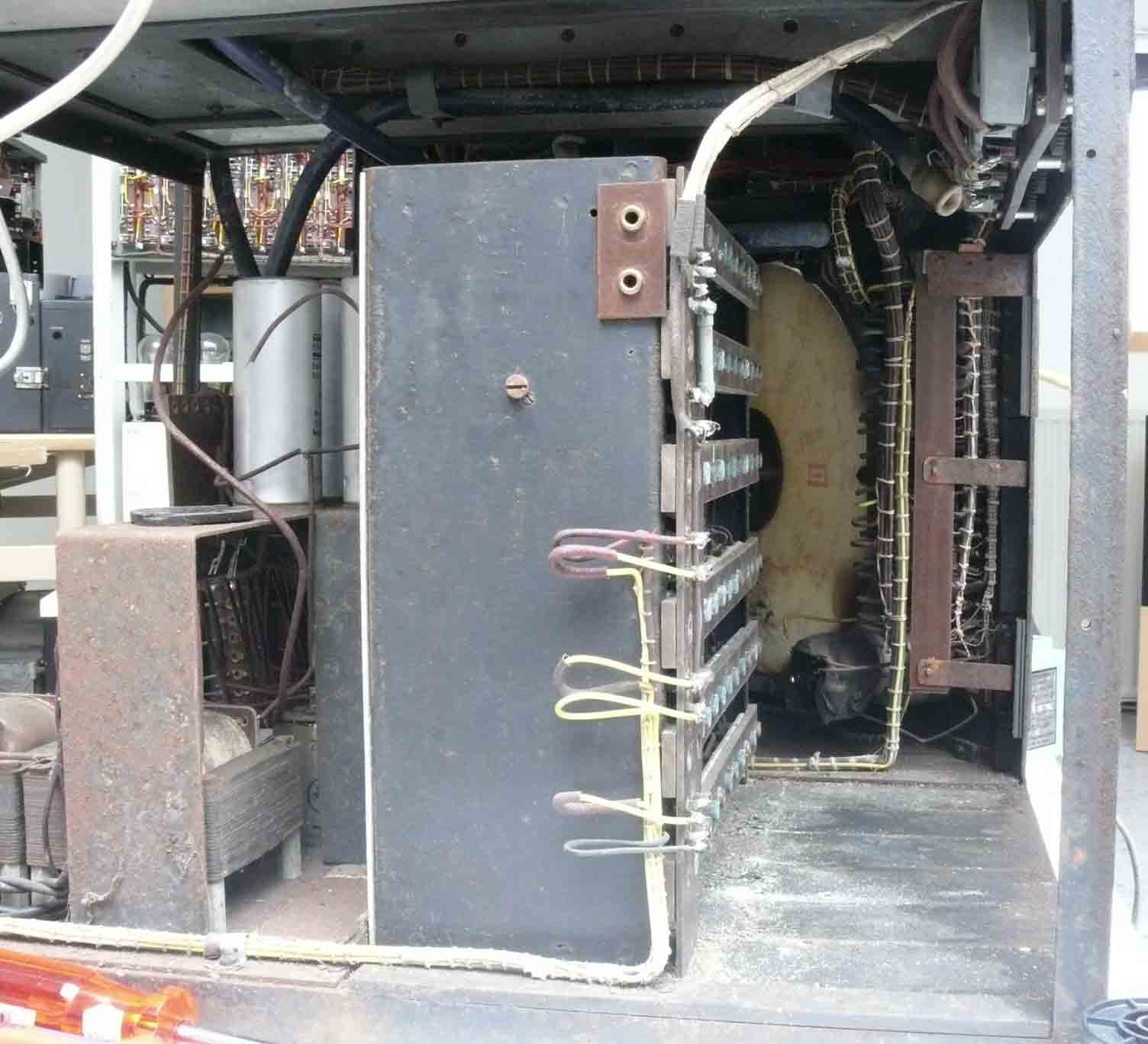
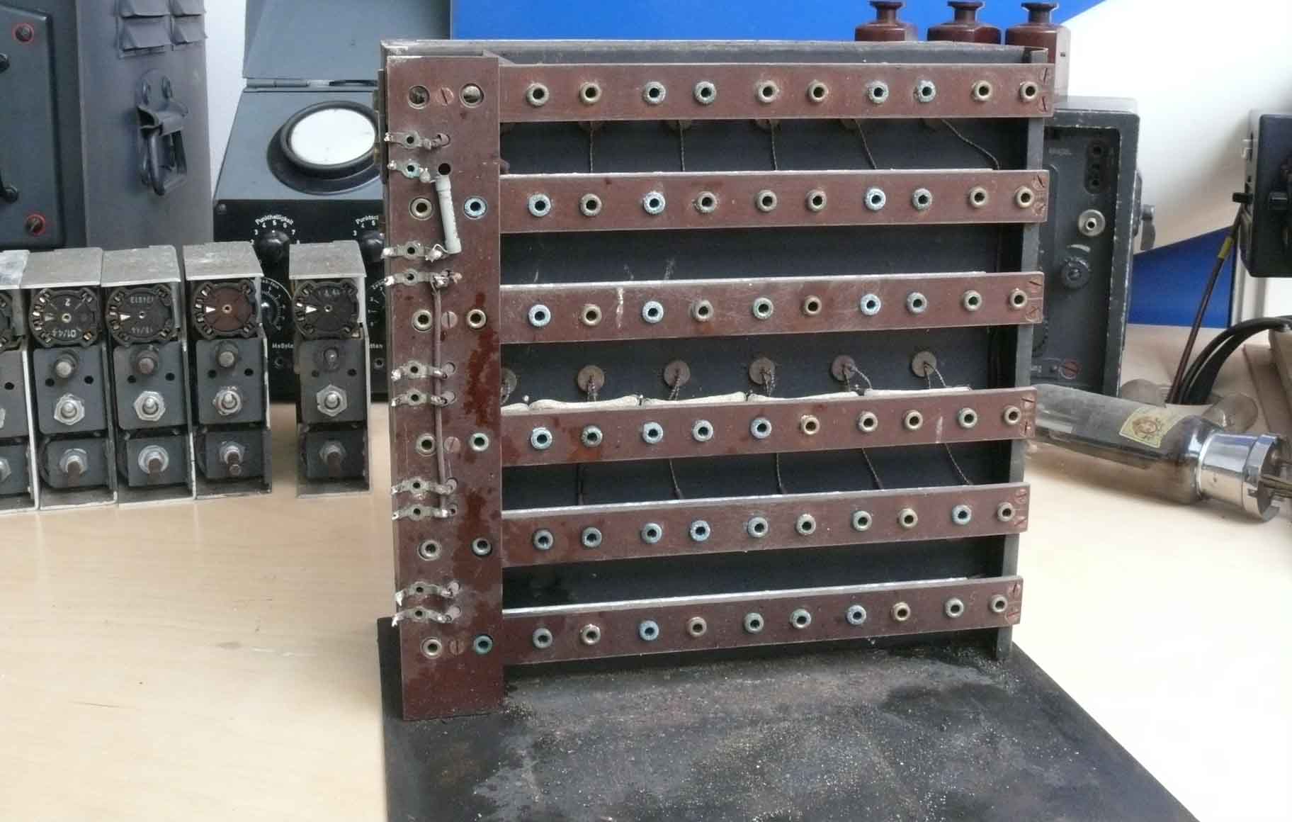
All 11 plug-in modules have been removed and we are looking at their counter contacts
It proved to be quite difficult finding out how this unit could be removed. My first though was, that it was hold by means of screws accessible from underneath. I couldn't find any sign of it, thus there must be another way. With the support of Ton Bronsgeest we finally managed to pull it out off the frame. Though, as we will see everything related to the Nachtfee device all is different from what one might have thought.
The second step is, to de-solder the 9 wires
Counting from the top, two are the only signal screened cables, the wire next going downwards, is their mutual ground.
The 6 wires then following has to be for the 12 V filament - the HT of which I guess is about 250 V the other 2 wires belong to the thermostat system (although, their order of succession is not yet known).
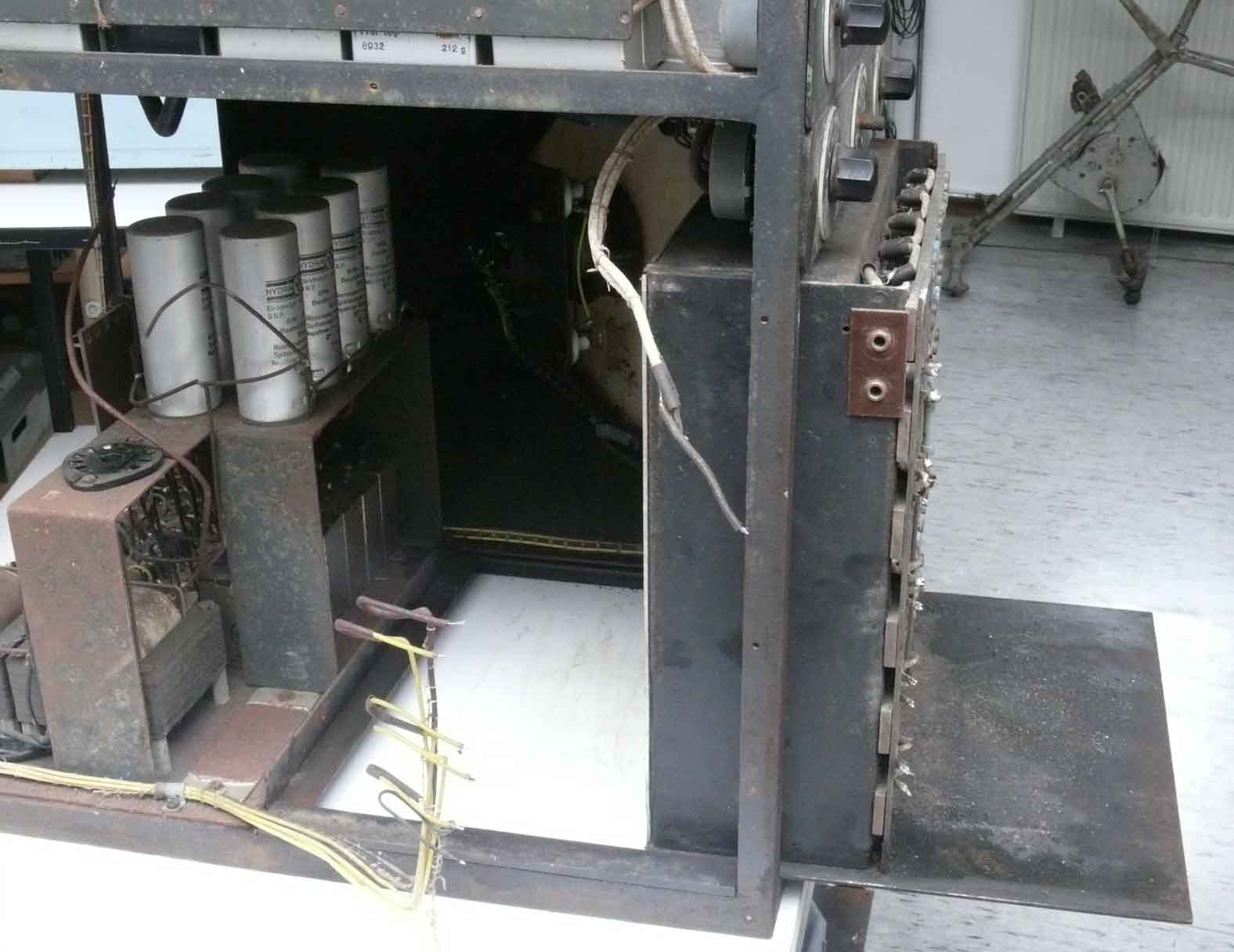
We finally found the correct way of pulling the frame out of the main chassis frame
One of the two upper screened cables runs to the next switch
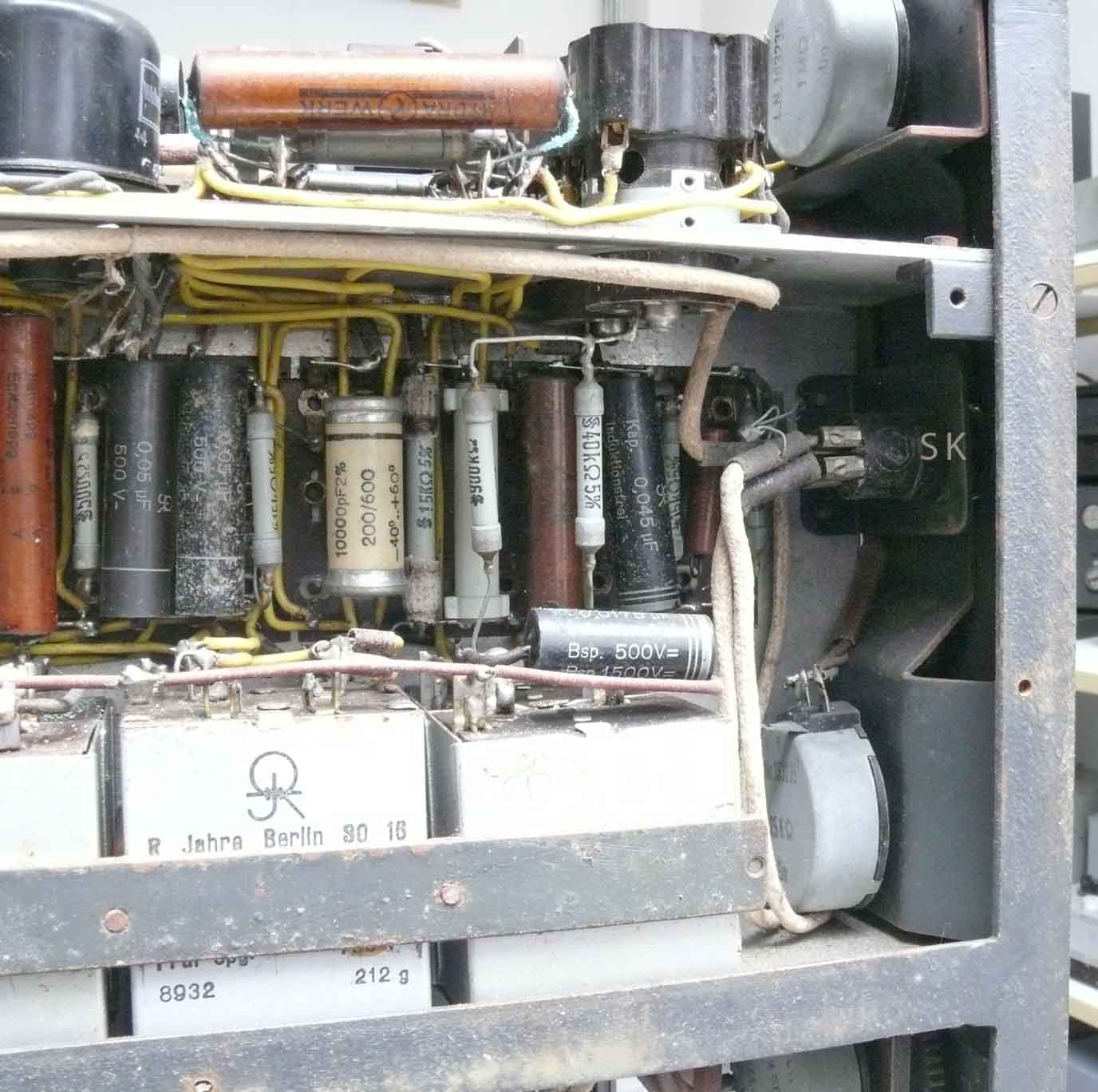
The switch marked 'SK' is a push-button at the front panel marked with: Frequenzkontrolle (checking frequency)
The second screened cable 'P' originating from the now de-soldered contacts of the to be investigated module runs towards the stage left of the dual beam CRT stage. Most likely to- or coming from valve number 6 (EF14 a rather high slope type)
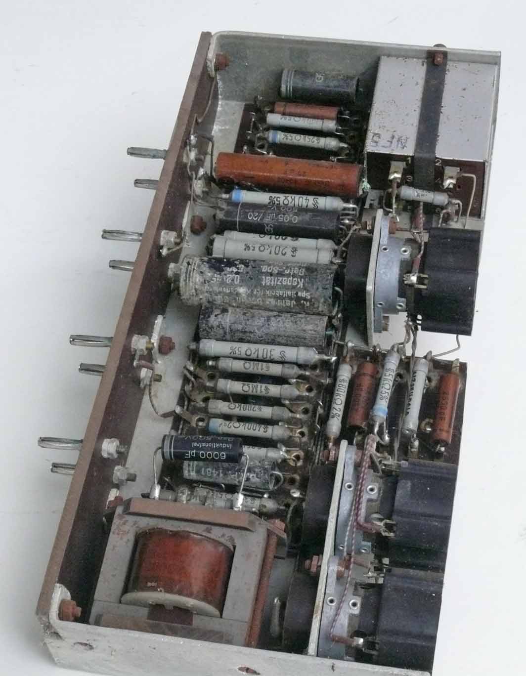
Our next step undertaken was making photos of the bigger plug-in module
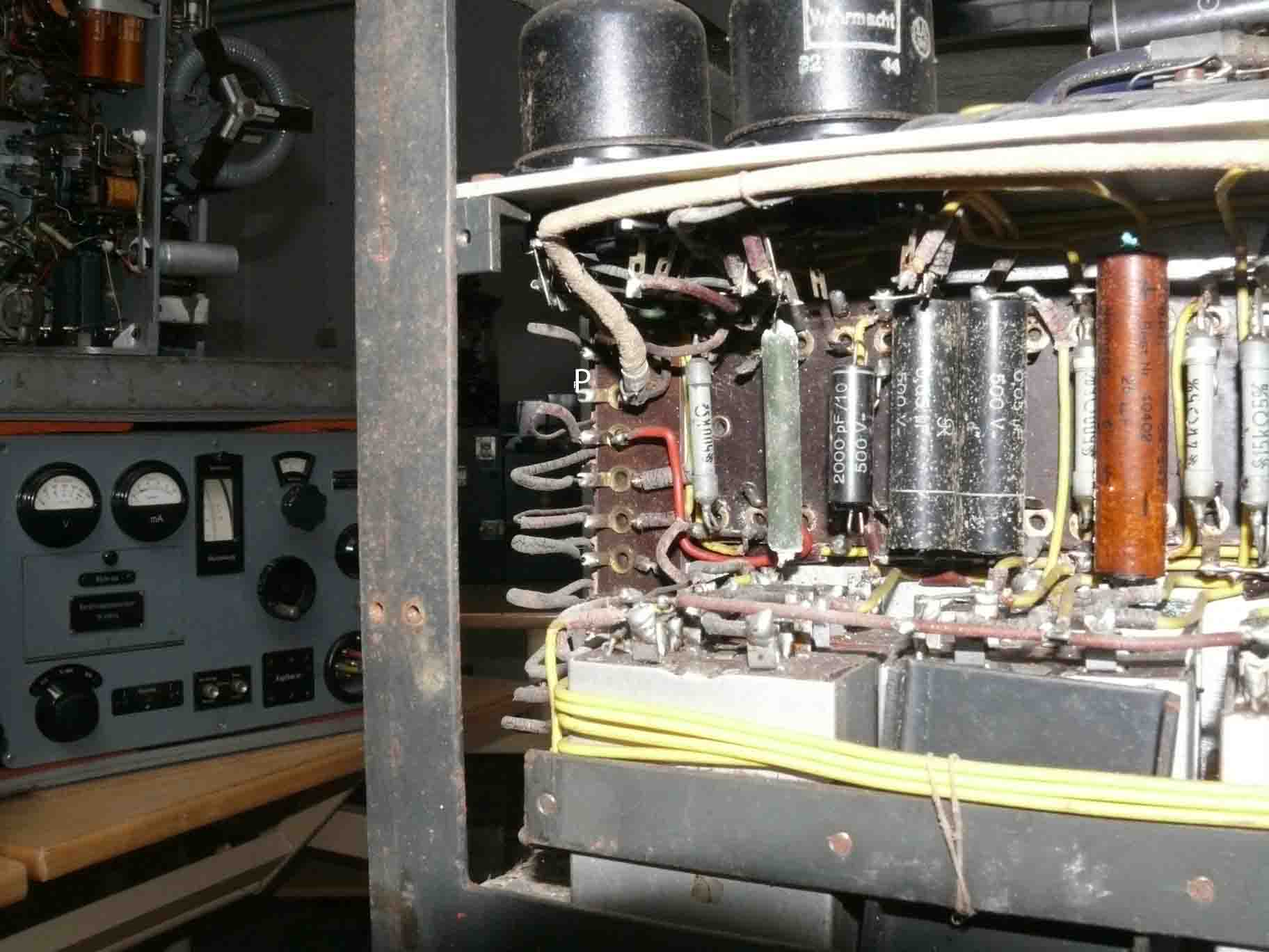
The transformer nearest to us, is designed for higher frequency application, as it uses a dust-core. Not visible, is that the coil is kept a bit free from the dust-core, maybe lowering its capacity against ground, as to increase its operational bandwidth.
Please notice that the coil of the upper transformer is having some space around its (dust) core
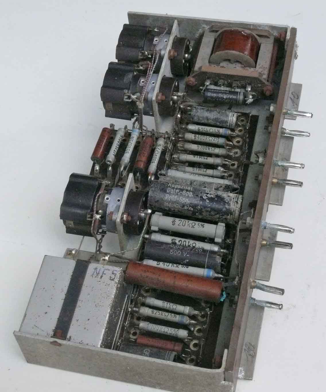
'NF 5', is not yet understood. As Trenkle mentioned, although I believe he doesn't fully have understood the Nachtfee technical implications himself, that there might have existed 5 Nachtfee systems, and my likely guess is that figure '5' is equal to (Roman) 'V'.

Although, I cannot prove it, I guess that the roman V and our Arabic 5 might implicate that it concerns set number five
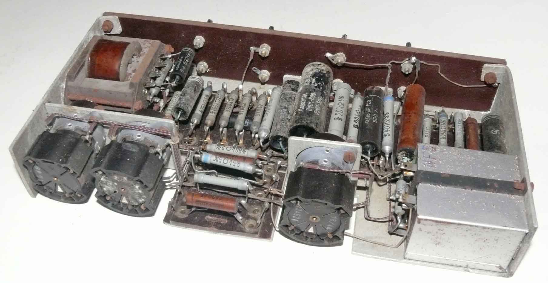
Again viewing from a different perspective
The next step undertaken:
Putting the central module on a table for photographing
The 10 small plug-in modules are standing on the left-hand side.

The white paint at the plate locking screw indicates that the unit never had been opened!
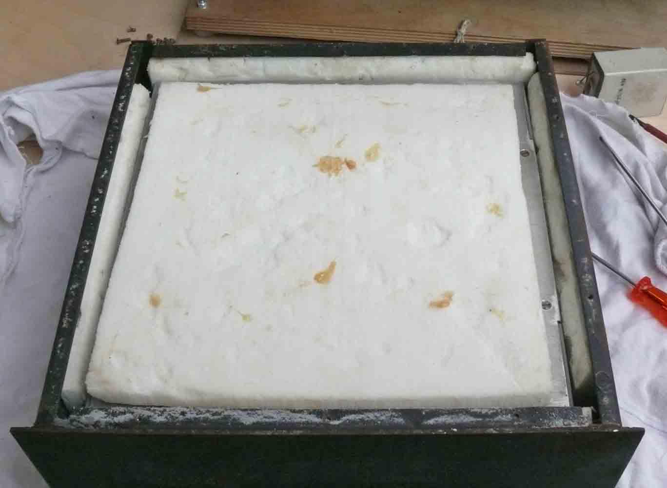
Underneath the plate I discovered a Styropor like plate
I guess, however, that it is made of on a kind of processed glass-fibre. Why should they have done this?
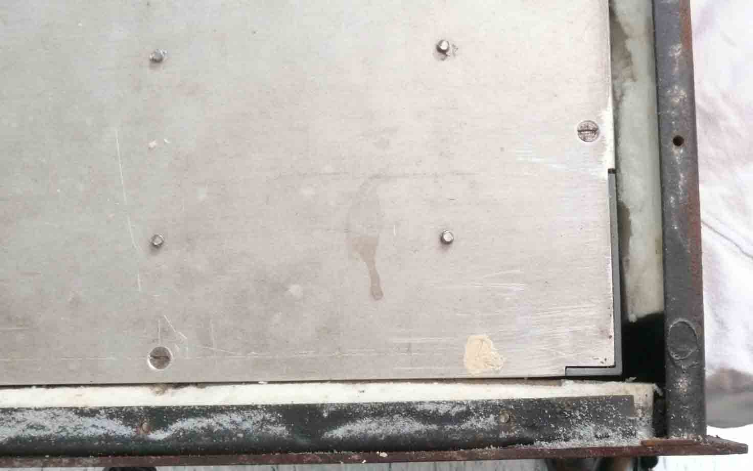
The white colour seal is our second proof that this module has never been approached before
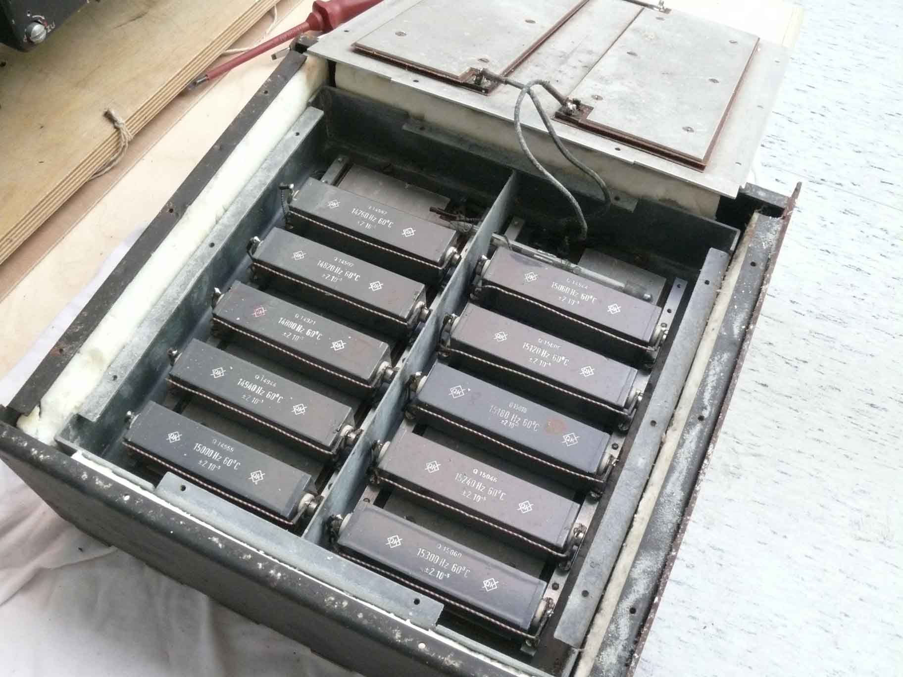
Opening its lid my breathing stopped virtually!
10 longitudinal quartz resonators operating in a spectrum around 15000 Hz, each one separated by 60 Hz. Working temperature 60° C. That is where the insulation is about for. I also understand why the outer frame is made so solid. The heaters are mounted inside of lid number two.

From left to right upper row, than the lower row:
15000 Hz Channel 5
14940 Hz
14880 Hz
14820 Hz
14760 Hz Channel 1
15300 Hz Channel 10
15240 Hz
15180 Hz
15120 Hz
15060 Hz Channel 6
Producer was: QK which stands for Quarz-Keramik a to Rohde & Schwarz related (affiliated) company; established by Handreck who had left, after a row, Hescho (I was told that he was a quite difficult person to deal with). Handreck was the main inventor of temperature controlled ceramic capacitors.
It is quite normal to use longitudinal quartz resonators for this quite low frequency. One might also believe it is a quartz-filter, but in such a case in- and output should be separated soundly, which isn't the case here.
Please notice also the mercury-contact-thermometer for controlling the 60° C oven temperature.
My next move was looking how the two order (commando) pointers are being fit onto the single servo behind the plexiglas (perspex) circular window
Again, here also things are different from what one might have thought firstly.

S = the servo (Drehfeldgeber); G is connected onto the big order pointer; K is being linked onto the small pointer
Intriguing, is that the big pointer is not linked with the servo at all! Only the small pointer does have a mechanical connection.
How does this information is fitting together?

Let us take a closer look at both pointers
Both have a central line. My guess is: that both lines should be brought as to be virtually a single line.
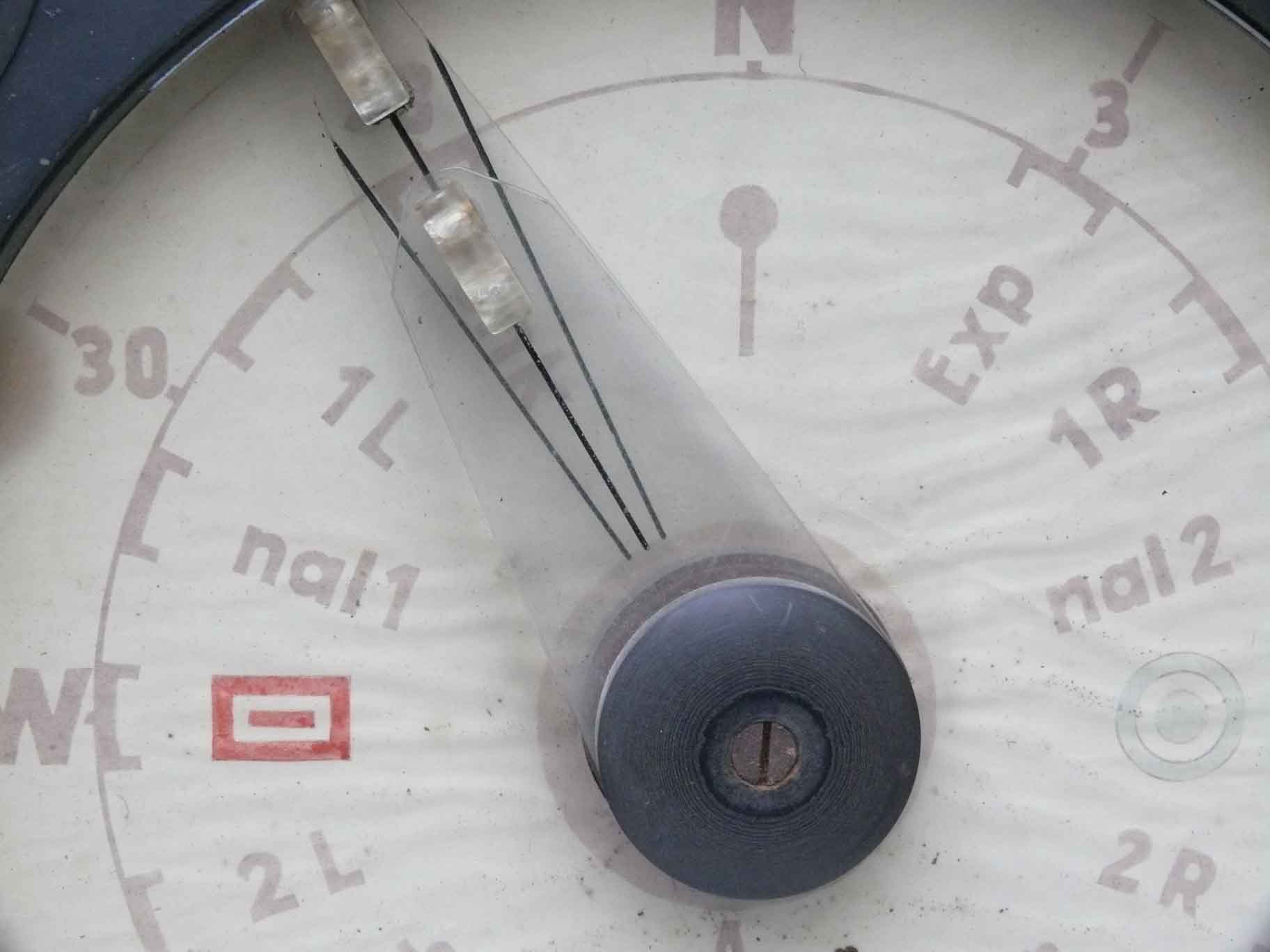
The layout and construction is such that it is very simple keeping both lines covering
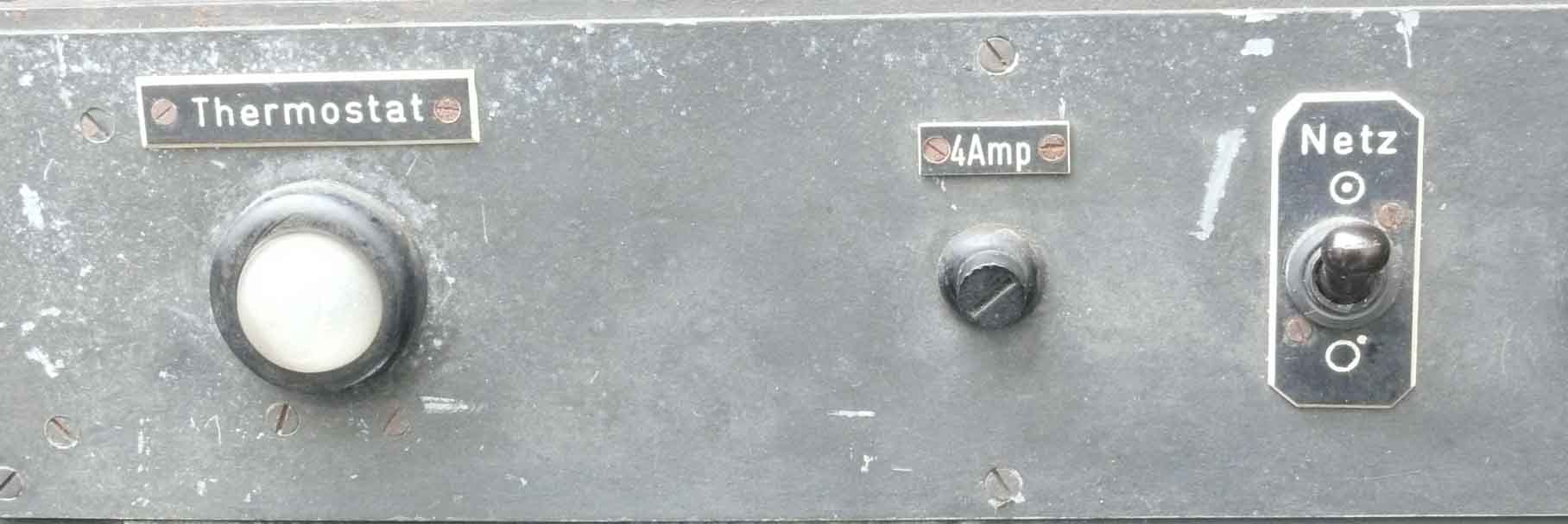
The heating operation of the 'Thermostat' is indicated at the front panel
I have not yet investigated whether the thermostat works fully at 220 V ac. A quite dangerous situation, though, viewing the time pressure in which this system had been created, one can expect everything. As the thermostat has a different (independent) 220 V ac input, it might have been that for this occasion they have considered a separating transformer (Trenntrafo) (1 : 1) as to become free from the 'hazardous power-line'.
Calling again for an American citizen, who very kindly is supporting us with tracing any form of information. Nachtfee was shipped (as being captured equipment enemy) to the United States about 1945 and likely someone has done some investigations on it. According its previous owner, he obtained it from someone in the vicinity of Dayton (Ohio).
![]()
Please type in what you read
Please notice also our: query page
Please don't forget to use the handsome: Nachtfee Chronology page
And, the PowerPoint progress page (converted into PDF)
By: Arthur O. Bauer
Please go back to, or proceed with: Nachtfee-MLK-lab. survey 4 (Status 13 December 2011)
Please go back to, or proceed with: Nachtfee Survey 3 (Status 8 December 2011)
Please continue, or proceed with: Nachtfee survey page 3a (Status: 26 December 2011)
Please go back to, or proceed with: Nachtfee starting page (status: 17 December 2011)
Please consider or go back to: Nachtfee FuG25a project - investigating how the Nachtfee data was conveyed towards the aircraft display (status: 18 February 2012)
Please go back to, or proceed with: Handbooks papers and product information
![]()