
Jagdschloss - Kreuzeck and System Survey
Initiated on 12 May 2014
Status: 7 September 2015
By pure coincident I came across a module that the owner did not recognise; although, he is most acquainted to these maters.
Instantly the idea was born to obtain it, and initiate a new system survey. Which I baptised:
Jagdschloss - Kreuzeck System Survey
The Jagdschloss system carried GAF designation FuG 404
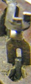
Shown is the front panel of the Kreuzeck receiver unit
All signs point into the fact that it has been stored for a long while in a quite poor environment, not sufficient to preserve it in a museum like manner.

Label information:
Geräte-Nr. 124/4221A (actually representing the construction drawing number)
Anforderzeichen Ln 20542 (GAF stock number) The 20000 series was dedicated to GAF radar related techniques, generally.
Werk-Nr. 70659 It might indicate that the serial number was 59, as I cannot instantly imagine a more likely figure combination; particularly bearing in mind that about 80 systems were scheduled firstly.
E 67 may, after
due consideration, also provide a plausible combination included in the
production number 70659.
As to cover production figures all kinds of character combinations might have
been used. However, it is not very likely that we will ever get the 'true
production key information'.
Please consider later (very) down this page what we have discovered on E 67! But please proceed first with this survey report.
Please do notice, that particularly after the Bruneval Raid of February 1942, all indicating plates or labels had to be mounted in a way that it cannot be removed without destroying its information content. Since, in most cases they replaced them by water-stickers (I do not know the appropriate word for it). Or, like in our case, simply painting the necessary information onto the apparatus frame.
One of the reasons why I am particularly interested in this receiver, is the fact that it was redesigned by Siemens (then legally known as: Siemens & Halske or S&H)
GEMA's basic radar concept was used in various German radar systems, like: Freya - Mammut and Wassermann, to some extent also Seetakt. Late Fritz Trenkle pointed that the performance of the original GEMA apparatus design could not cope with the enhancing apparatus specifications. Most likely owing to the fact that GEMA was more an engineering than a scientifically led company. Siemens became involved in boosting the performance of the various radar sections (also incorporating advanced antennae designs).

Quoted from the wartime training manual to the Jagdschloss A system.
The original Freya like concept relied upon a more or less fixed operational frequency, say within 120 - 125 MHz. Owing to increased jamming like 'Moonshine', it proved to be necessary to spread the operational spectra. Increasingly important, changing the system frequency as quick as possible; not loosing contact with the current radar target under observation.
Intriguing for me, and maybe for those interested in valve (tube) application particularly, is the adoption by the Siemens designers of the Philips EFF 50 and EFF 51 series. The '50' series was widely adopted in Britain and culminated in the EF 50 which got the military CV 91 type designation.
Not generally known, is, that the first Philips valve concept differed a bit from what most of you know. The very first series used not the common pin configuration but the valve-base contacts were half-way bended for 90°, as to secure that the valve was mounted shock-proof in the valve socket. The next version was more like we are used to. However, not entirely confirming to the international 'loctal' specifications. Still maintaining a kind of vibration-proof mounting.

The way it is being fixed is by a particularly shaped 'spigot', which we call in Holland a 'loper' door-lock-key
It is quite clear that this kind of spigot allows a valve-base-rotation when being inserted.

According the German manual: to fix it one has to rotate the valve clockwise and removing (demounting) is accomplished by an anticlockwise turn (I guess about 5 à 10 degrees either way)
For me the first time that I come across the notation that there existed a special tool for mounting/demounting. Zum Auswechseln der Röhren 1 und 2 (EFF 50, 51) wird ein besonderer Röhrenzieher mitgeliefert.
Quite informative for some experts might be the production number 295 U. I learned once that from later Philips production figures in the 1950s such kind of indication is providing the valve type + where and when it once was manufactured. I guess, however, that 295 U is more pointing onto a (production) batch number or that like. Maybe it constitute an acceptance information. Vaguely visible is the designation '050' which might point onto a guarantee number. Also just recognisable is the fact that the trade mark is directing to Valvo. But Valvo was the German representative of Philips Eindhoven. Whether it our valve was made in Hamburg or Eindhoven we cannot answer.
We know from wartime espionage reports arriving in Britain that Philips produced quite a lot of EFF 50s and EFF 51s.

Copied from the document in our possession
It is clear that they ordered of each type EFF 50 and EFF 51 type 4000 samples. What can we learn from these figures?
A guess: 125, maybe 200, Jagdschloss systems were once scheduled, considering also that in due course: Mammut, Wassermann and maybe later Freya radar should be upgraded with this receiver concept; bearing in mind also the necessity of spare valves, 4000 samples is constituting a quite realistic purchase figure.

Viewing the EFF 50 from a different perspective
The EFF 50/51 series use, like the standard EF 50 base 9 pins + the centre spigot for additional screening (connected galvanic onto the chassis or frame). These versions do not possess a metal screening cover, though, fully rely upon an internal mesh-screen.

The internal screen is clearly visible
In 2006, 2007 and 2009, I visited, with a group of IEHG valve collectors, the vaults of the Philips Museum in Eindhoven (De Hurk) and asked them about sockets for the early valve types. They told me, that they possess non of them.

Viewing the EFF 50 valve socket from above. Clearly visible, the valve contacts are operating when the valve is in its locked position when it is being rotated clockwise
In my opinion, like the regular Philips loctal base of those days, not very much impressing in respect to contact reliability! Philips might have made the least reliable loctal valve sockets ever! Imagine, the contact are only relying on just the very small edge singly of the contact-pin perimeter.
(4)
On 22 July 2014 I got an e-mail from Heinz Trochelmann, who told me, that 'oh wonder', he found in his collection such a valve socket. His photo shows the problem very clearly. We may well assume, that its concept was rather poor, as no provision was implemented as to fix the valve position for operational purposes.

Please consider the socket in front
The valve base contact just right of the centre has some quite slight shape which should hold the valve pins in its operational position, but when this is the only provision 'Philips' provided, then it is of a very poor design! Even when we take into account that its concept goes back to ca. 1941. Even this provision was much better than the regular loctal-socket used in commercial equipment or radios.
My attention was drawn to the aspect of: how were the valve base contacts reliably locked within the valve socket. As I already have expressed, Philips made hopeless poor loctal like valve sockets (Fassungen).
A magnification of a pin-contact of the previous photo
These two small spring-brass strips constitute the entire pin-locking (fixing)!
The central lock arrangement (spigot) is also a great matter of concern! Even small amounts of vibrations will definitely 'self un-locking' (ejecting) the EFF 50 or EFF 51 tubes.
Please notice the previous photo. It is clearly visible that the contact strips are rather small, as these are only having about the same strength as is having one of the pertinax plates.
With some good will, the electrical contact of the central 'key and central contact' is recognisable.
Can you find any HF matching contact-load in the central spigot hole?
What kind of solid ground contact can be established by this means?
Lets us turn our attention onto our Kreuzeck receiver module.

Viewing the left-hand side (viewing the front-panel) of the Kreuzeck receiver module
Maybe not entirely visible, but the transformer is a quite heavy one.

Considering the right-hand side of the module
The proportions of the transformer can be better judged.
Please notice the tiny PVC coloured wires attached onto the test selector switch. PVC wire insulation was later in the war widely used for military applications. Particularly in respect to new designed equipment of high standards.

Viewing the rear side of the Kreuzeck receiver module
The rather heavy 70 ohms coaxial connector is to link onto the antenna system. The quite small coaxial connector down is providing the 'video' signal. Its coax-cable-diameter inside the Kreuzeck module is having an extremely small diameter. I cannot remember having encountered such one before in any German wartime equipment I ever came across.
The three contacts just above '110' is constituting the 220 V ac power connection. This means that the Kreuzeck receiver is to operate 'stand-alone'.

The Kreuzeck receiver schematic (Schaltbild)
Let us take a view in what environment this module was being operated.

The Kreuzeck receiver module being pulled out a bit (on the far right-hand side)
Left of it, with the three circular scales is the measuring-chain, consisting of a bank of selectable delay-line (taps) as to determine the range of a target. The unit with the two circular disks facing just outside its die-cast cover plate is the 'Gemse' receiver which constitutes the ground IFF receiver.

Left of it viewing the rear the the fine-range control scope (A type presentation)
We might not get this type but we hope to swop in due course a comparable GEMA unit used in conjunction with regular Freya or comparable systems. Please remember, that only a few Jagdschloss system became operational. Finding these modules is hardly possible. That we possess now the Kreuzeck receiver as well as the Jagdschloss low-band transmitter version is already a miracle! See also the findings on 'E 67' further down!

A photo of the wide-band Jagdschloss transmitter (low band spectrum). Code-name Eibsee
Please notice the four pointers in the upper row first, then turn you attention towards the next photo.

These may correlate with the red pointers I - II - III and IV. These spectra or bands were called: Insel. I guess that the two outside sharp edges on either side of the red centre pointer constitute the tuning limits of a particular range or 'Insel' (band section)
(A)
After viewing the information placed previously on our website, I discovered something most astonishing!

This label belongs to the Eibsee TX we obtained three years ago.
Please compare is with the label information below.
What does it have in common?
Both carrying the designation E 67
I phoned Günter Hütter instantly and asked him where he got his device from. His first response was, from Austria quite a long time ago. Then I mentioned that he once obtained an X-Gerät, like ours, from England. He responded: Yes I remember now, I got it from England via my Swiss contact though, this was quite a long time ago!
It is thus most likely, that both our Jagdschloss transmitter, as well as the recently obtained Kreuzeck receiver module, originate from the same source. Namely both from late Graham Winbolt, who possessed huge stores of historical technical matters. We can be for 99.9 percent certain that either module originate from the same Jagdschloss radar site.
I regard this being more than a coincident.
At present I tend to the consideration - that our Kreuzeck RX is having production or serial number 65 and the Eibsee transmitter carries serial or production number 72; or respectively 59 and 25. The one who knows it better please come forward!
It is also likely that both devices have been manufactured by Siemens & Halske Berlin, as
eas stood for:

Particularly considering the quite identical production numbering

For today closing with the a rear view of the Eibsee transmitter which equals the one we possess.
On 18 May 2014
Part 2
My due consideration was, what should we do - leaving everything as it currently is, or accessing the modules?
I decided, at least, to investigate what is inside, because this is the only way learning what the state of technique was, and also having a chance of taking measures preventing further deterioration. That action should be taken became instantly clear as at least 50 to 60 percent of the bolds (screws) necessitated quite high force to remove them (often in a non repairable way). Apparent is also is that most outside plates could only be removed when the receiver section was pulled out of its main chassis.

For it two pairs of bolds has to be removed, two at the upper top- and two, shown here, at the lowest front-panel-side
By the way, the longitudinal red line might indicate that this unit or module was a secret device.

I bothered first whether the rear coaxial antenna connector should be made free too, but forgot that we deal with a German designed device. The design concept was foreseeing this and did what should be done - the coaxial tubular line is provided with an additional coaxial coupling (Trennstecker)

In the centre its sound construction is good visible
It is also evident, that at least some of the chassis need particular attention.

Viewing the tuning capacitors of the receiver front-end section. That they each consist of a dual system is owing to the fact that the two front-end stages are electrically designed in 'push-pull' (EFF 50 and EFF 51)
The poor state of affairs is luckily found more at the outside than inside the compartments.
Viewing the rust (Fe oxide) and the thin Cu plate we should investigate whether these are actually made of Fe being plated with Cu. This technique became known in Germany as: Staku. (Sta - Fe and ku - Cu). Saving quantities of Cu, which was a scare strategic material. Why using solid Cu while the HF currents are only 'passing through' a view microns at the outer skin of the conducting layers (skin-effect)? I tested it and my estimation is true.

It is quite evident that much care was taken in filtering the lines from the supply- onto the HF front-end sections. Siemens was a world champion in HF 'suppressor filtering'! The coaxial design was in those days the best way accomplishing this objective
It is also evident, that accessing the front-end circuit around the valve socket is not everyone's job!

Photo taken after removing the screws. The few new screws remaining being adapted temporarily. Viewing an IF stage mounting plate, which' purpose afterwards became clear. It is also evident, that something should be done against the poor state of the various chassis sections outside
The four brown rings constitute a manner to insulate galvanic the IF module underneath from the main metal chassis. As to control a proper electrical ground or earth contact to the main chassis.

Before the module can be accessed its interconnecting wires have to be disconnected first
Viewing this photo it becomes clear to me, that we only have to deal with a single screened cable. An amplifier stage needs two, one for the input and the second one for its output. This module thus constitutes a local oscillator stage!
Please notice: that the right-hand side open wire above is constituting the single ground interconnection onto the chassis frame.
During the course of this survey I decided, considering the poor state of the chassis outside, we should explore the fact that the chassis is in this state good accessible. We therefore will also do some work on cleaning the Cu plates and/or intersections. It might not be possible to access every hidden space, but at least we should try to clean it where possible. Accessing quite hidden places is delicate, as acid residues cannot be removed properly!

The Cu plate with attached module being removed
The (scooped) grey top plate actually is removable from the front panel (written on it 'Rö 10') as to access the oscillator valve (LV 1).

Among the items we obtained from late Graham Winbolt were also LV 1s carrying the same, or at least similar acceptance stamps, which underlines my suspicion that Graham's LV 1 valves and the ultimate source of Kreuzeck receiver module originate from the same British source (captured German equipment and spare parts around)
The trimmer just left of the LV 1 likely is to adjust the correct oscillator frequency as to match onto the second IF frequency path-band. This module is at its top side screened off by an extra (removable) cover Cu plate.

With some imagination it is visible that the mounting plate is not directly attached onto the IF module but having a few millimetres space
By this means the IF module virtually floats against the main chassis, providing the possibility to chose the most suitable earth or ground connection point. This is often necessary as to prevent for unwanted earth (ground) currents.

Viewing the electronic components belonging to the separated IF stages
Please notice the high quality Sikotrop capacitors.
Let us close, for this occasion with considering the EFF 50/51 valve socket again.

Determining the angle of rotation for fitting and removing the valves
Roughly, I measured about 10 degrees rotation angle. Exact measuring was hampered by the fact that rotation of a duplicate vector-pair also caused a displacement against each other. But our estimation will be about accurate.

Let us focus our attention onto the actual shape of the spigot lock
Maybe not entirely clearly visible, my opinion is that Philips have created a quite unreliable valve locking.
What should have been done is shown in the next drawing.

Example A is what we currently encounter, example B is as, in my imagination, it should once have been designed. Of course smoothing the lock-edges might in some way have been necessary. My objection only is to explain the locking principle from my perspective!
Not known however, is the fact whether it actually genuinely was designed this way and that the 'virtual spigot-lock' was destroyed by those unaware the way how these kind of EFF 50/51s should be mounted or de-mounted. Nevertheless, looking carefully at the current sate of affairs, I am afraid that my preliminary suspicion still stands, as there is not the slightest remaining indication that something was once destroyed by force.
On 20 June 2014
Extension 3
Discussing the transmitter is quite static, why not getting an impression how it operationally may have looked alike?

The filament of the two TS 41 transmitter valves being powered
Is it dangerous? No, of course not! Only the filaments being supplied with 10 V, consuming 10 A each, this our power supply has to provide at least 20 amps.

Getting an impression how this module fits into our exhibition space
On the right-hand side down we look at the Freya / Seetakt (Jagdschloss?) main power supply. The scale was meant for changing frequency within determined bands (Germans called it: Insel I - IV)

(5)
On 7 September 2015
We have fit our recently obtained OB-Geräte Einsatz onto the current Jagdschloss display. Although, we only possess some of the Jagdschloss modules.
For an extended photo series of the OB apparatus -please visit Exhibits-details 17
Let us remember first how once the 'low energy' modules were being placed together

Let us compare module marked 'RD' with the next photo
This photo have been copied from our main Jagdschloss webpage

Almost equal, although, the black box and related mechanism being omitted in the previous photo
(AOB)
This provision constitutes the on-off switch.
However, we do come nearer with our current display setup

From left to the right: the Kreuzeck & video amplifier module; next the Gemse IFF receiver; the new OB-Einsatz; and on the right-hand side the Jagdschloss transmitter code-name Eibsee
I must admit - that the succession of module do not reflect the genuine state of affairs as being shown on the wartime photo

Viewing it from another perspective

Viewing it a bit more from a centre position
Referring to the first wartime photo, from left to the right we notice:
RX (Kreuzeck) - Gemse IFF - RD (OB-Gerät Einsatz) - and not visible on that photo the TX Eibsee (once providing 100 kW transmission pulses)
During wartime days the Kreuzeck receiver (RX) and the TX (Eibsee) were once part of the same radar station. Notice for more details: Kreuzeck and RX labeling
I honestly guess - that we may have reached a limit; because bringing this altogether was already hardly possible - accompanied with a great deal of luck. Where to find additional GEMA modules? These kind of artefacts seemingly disappeared from earth.
One reason - no one can use it; and the modules do not attract peoples mind. Albeit, that during wartime days, Freya - Seetakt and their derivates played an important role in the German radar history.
Though, who is daring?
To be continued in due course
By: Arthur O. Bauer
Back to, or proceed with: Jagdschloss main page
![]()