
Page initiated on 6 March 2019
Current status: 18 March 2018
Reconstruction of the ”Funklande Gerät FuBl 2”
By Hans Goulooze
Introduction
This is a summary of a reconstruction and some verification of an military aircraft blind landing or bad weather landing system from around 1939, also known as FuBl 2.
This system was an initial design by the German Lorenz Company. The present article is concerned with military equipment manufactured by Telefunken.
Short functional description of the Lorenz landing system
Its function was to enable the pilot to approach the landing strip accurately (although not blind) from a distance and also, to the end of the approach, to get information at 2 locations on the distance with respect to touch down. The FuBl-2 required specific ground based equipment.
This landing system was an addition to the long and medium wave direction finding equipment (as an example the APZ 4 or the APZ 6), as available at that time in most larger aircraft.
The long and medium wave direction finding equipment was used for way-point navigation, based on beacon or broadcast transmitters of a known location with respect to maps and was essential for reaching an optimum location for picking-up the guiding system signals.
The FuBl-2 ground based equipment has been no part of this exercise but it basically consisted of a 500W transmitter, tuneable to around 34 frequencies or channels from 30 MHz to 33,3 MHz (Ansteurungsfunkfeur or AFF) and associated switched vertical dipole antennas placed at the end of the airfield runway (see Figure 1 a, b, c).. The frequency or channel was specific for a landing strip or airfield.
In addition, two 5W transmitters (Vor/Haupt-Einflugzeigensender) at 38 MHz each with a distinct modulation, provided the distance to touch down at 3000 m (VEZ) and 300 m (HEZ). Both signals would sequentially be heard by the pilot, only during passing overhead the respective transmitters and antennas in addition to the AFF signals.
The AFF was constant amplitude modulated with 1150 Hz and the carrier was keyed. The switched dipoles of the AFF provided 2 antenna lobe patterns with, as experienced by the pilot through the on-board equipment, Morse dots (1/8 sec. 1150 Hz, for a deviation to port) and dashes ( 7/8 sec. 1150 Hz, for a deviation to starboard) at the extreme off-course positions respectively. A gradually more continues tone was heard by steering the correct coarse, in line with the landing strip.
A schematic overview is provided by Fig. 2.
The course information was available through head phones as well as visual by a cockpit moving coil indicator (AFN 1 or AFN 2) showing rhythmical Left or Right deviations from the correct course. The cockpit indicator second moving coil instrument provided visual information on the signal strength and therefore some crude information on the longer distance to the AFF. Based on the antenna radiation pattern also height information might be concluded on the field strength. However, it may be assumed that the indication of barometric height meter was decisive.
The VEZ and HEZ signals were amplitude modulated and the carrier was keyed:
- VEZ: 700 Hz, keyed in dashes of 0,4 sec.
- HEZ: 1700 Hz, keyed in dots of 0,066 sec.
In addition to the audio VEZ and VEH signals in the headphones, a neon light was ignited, placed in AFN 1 indicator, for the duration of the incoming signals, dots and dashes.
Fig. 1a: The three vertical antennae of the (Anflugfunkfeuer) AFF

Fig. 1b: Switching arrangement of the 3 antennae

Fig. 1c: The resulting radiation pattern, related to the dots
Some history
Historically the FuBl-2 was a further development from the FuBl-1, a receiving system, although a military development, fully based on the earlier well known Lorenz approach system, widely applied by the civilian airlines. The earlier military system (1937) the FuBl-1, consisted of the EBl 1 (AFF receiver) and the EBl 2 for the reception of the VEZ and VEH signals and audio processing for both receivers.
The EBL1 was a 2 stage receiver, tuneable to 2 frequencies, with an audion detector and the EBL 2 consisted of 1 audion only, with in addition audio processing, for both receivers and indicators.
The FuBl-2 (1941) was as a system similar to the FuBl-1. However, the EBl 1 AFF receiver was replaced by the EBl 3, a super heterodyne receiver with an increased sensitivity, that enabled the reception of the AFF at 70 km at a flight height of 200 m. The original EBl 2 was adopted in the modified system without changes.

Fig.2 : Approach to the landing strip (Landungsfunkfeur)
Three versions of the EBl 3 were designed; the EBl 3H ( Handbedienung) with 34 channels, for tuning by hand and the EBl 3F (Fernbedienung by the FBG2 remote control unit) with 33 channels, that was placed in an instrument bay and controlled from a distance by the wireless operator. Also the EBL 3G is mentioned in documentation, that was tuned by the FBG 6 remote control unit. It is suggested, it included a fine tuning facility for +/- 20KHz .
During 1944 a UKW-Drehfunkfeurempfangsgerät (FUG 125-Hermine) was developed by the German Air Force (Lorenz)and the EBl 3F was, with some additions, such as an audio amplifier, applied as the on-board receiver.
Documentation and photographs.
A full field manual or system hand book is available that is concerned with assembling, operating and adjustments at level of the major components and system. Documentation on alignment or electrical alignment of the individual components has been lost. Please be aware that in addition to the details discussed and presented in-here, there is much additional information in the detailed field manuals:
Ref.1: D.( Luft) T.4058, Funklande –Gerät FuBl 2, Geräte Handbuch. Februar 1943
Ref 2: Fugb-25, Arbeitsunterlagen, Funkgerätelehre. September 1943
Ref.3: WB 160D (2000); Telefunken brochure, commercial, from around 1935, explaining the
Ground based approach system.
Photographs have been made by the author to highlight technical details. Some figures have been copied from this field manual and are reproduced in this article.
All equipment as shown and most of the documentation are a part of the collection of:
The Foundation for German Communication and related technologies. (http://www.cdvandt.org).
The FuBl-2, major components
The FuBl-2 is a self contained on-board aircraft system, powered from the aircraft battery. It comprises of the following units, originally located at different locations in the aircraft, see Fig.3.
See also Fig.4 for a simplified block diagram.
Overview of the major components, with the exception of the antennas, that will be shown later.
At left is the EBL 2, followed by the EBL 3F and the rotating converter U8, for the anode voltage.
At the right of the U8 are on top the resistance network related to the 26V battery or heater voltage. Below the fuses and switches for the 26V power.
On the foreground left is the AFN-1 indicator for course information and indication of the VEZ and VEH signals
On the right, the RBG 2 remote tuning unit for the EBL 3F. The FBG 2 belongs in the genuine “Funkertisch” underneath.

Fig.3: System components and wiring

Fig.4. Block diagram of the reconstructed FuBl 2
The following is a detailed description of the major components with the emphasis
on replacement, repair and realignment. All the major components were available with the exception of the relays box (Relais-Kasten), that switches-of the EBl 2 to avoid annoying the pilot during the remote tuning. The AFF antenna and the HEZ / VEZ dipole and related antenna adapters were reconstructed to mimic the originals. The system was integrated on to small plywood panels also with the help of replica’s of turn keys as originally used (Fig.21).

Fig. 21: Turn keys (3X), reproduced from original, for mounting unit EBL 3 to frame
Original connectors were available for all interconnections and in addition the synthetic rubber insulation of many of the original cabling was still in perfect condition.
Final verification of the system has been performed by reproducing the AFF signal, including the keying. The keying of the VEZ and HEZ has not been reproduced for verification.
EBl 3 F
The EBl 3 is a 7 valve super-heterodyne receiver consisting of preselection and an antenna signal amplifier, a mixer and local oscillator, 3 Medium Frequency amplifiers with 3 pass band filters and a diode AM detector.
The frequency of the heterodyne oscillator is temperature stabilised by the application of a ceramic coil former and a special winding technique (see Fig.5).In addition, a temperature compensating ceramic capacitor assembly is applied to the oscillator circuit.

Fig.5: Oscillator coil assembly
The output of the detector is fed into the EBl 2 for further processing and amplification. The automatic gain control for the EBl 3 is important, because high signal levels that may be experienced when approaching the landing strip. Also as a part of the alignment on the platform, the gain of the receiver was “normalised” by means of a potentiometer, setting the screen grid voltages of the High Frequency amplifier and the first Medium Frequency amplifier. The potentiometer is accessible on the front of the receiver. The gain control voltage is derived from the audio signal as processed in the EBL 2 (Fig.6)

Fig.6: Combined schematic diagram EBl 3 and EBl 2
All valves are the miniature pentode RV12P2000, also including the detector.
The EBl 3F is tuned by the interaction of the drive unit and the control unit FBG 2.
The original drive unit attached to the receiver, was unserviceable because of a missing electromotor and had to be replaced by a “spare” unit. This meant completely disengaging the drive unit, in this case also removing the cables and replacing them on the spare unit. In addition, the ceramic trimmers for the high frequency preselection coils and some resistors and capacitors were missing. All were successfully replaced.
Also, but not uncommon, all the chassis metallic cover plates had to be remanufactured to avoid unwanted signal coupling during operation.
Replacing the drive unit and EBl 3F receiver tuning alignment
The drive unit is mechanically aligned to the receiver chassis with dowels and pre drilled holes, assuring proper alignment of the spring loaded double gear wheels and the drive mechanism. The double gear wheels and the clamp to the ceramic shaft of the tuning capacitor (Fig. 7), are a permanent part of the receiver chassis.

Fig.7: Detail of motor drive unit for EBl 3
The correct relative channel tuning is mechanically provided by the wheel with tabs ( Fig. 8, Rast und Nockenscheibe).
YouTube films
Film 00012: Operating the remote control FBG 2, build inside the genuine Funktisch from a Si 204 aircraft; and also viewing the movements of the mechanism inside the EBl 3F receiver.
Film 00015: Viewing the tooth-wheel end the according (fast) switching contacts (like is contact 5) and levers and also the mechanism to prevent that channel 0 being selected, the audio will then be switched-off by short-circuiting contact 7 against ground. The blank-tooth is preventing that channel 32 can be operated.

Figure 8: Tuning wheel
The notch in the large lever provides in operation, the reference locking point for the respective tabs on the wheel, after actuating the tuning procedure by the FBG2
At disassembling the drive unit and receiver, the spring loading of the double gear wheels, directly attached to the clamp, is released and has to be restored at assembly, to avoid back-lash in operation.
In addition it has to be noted, that for tuning the receiver during bench testing or failure analysis there is no need to perform this with the FBG 2. By removing the front cover of the tuning unit, the locking of the large lever and notch may be overridden by hand and tuning may be performed manually by rotating the wheel with tabs.
The oscillator coil has been pre tuned by the manufacturer and shall never be modified.
The coupling of the tuning capacitor and the wheel has to be such that alignment of the oscillator, by the precision trimming capacitor ( see also Fig. 6), accessible at the front of the receiver, is valid for all other channel frequencies.
This complex procedure maybe performed as follows:
- Before removing the incomplete or damaged tuning unit, carefully note the position or the number of the tab in contact with the lever with reference notch or you may select in advance channel 1 (Tab 1/ 30 MHz and therefore maximum tuning capacitance).
- In case of a lost mechanical reference of the tuning capacitor with respect to the tuning wheel, observe the following: The tuning capacitor has no end points and may be freely rotated to left or right over more than 360 0C. The tuning capacitor is not visible and therefore the pre tuning may result in 2 different rotational settings of the capacitor. Observe the rotating direction of the tuning wheel and pre tune accordingly.
- Fully lose the clamp on the ceramic shaft of the tuning capacitor
- In advance, verify that the “spare” tuning unit indeed does fit into the receiver.
- Before placing the tuning unit on to the receiver, the 2 springs of the double gear wheel has to be pre loaded.. Both gear wheels have a hole each, when placing the holes in line with each other, the springs are loaded and the loading may be secured for the time being, with a steel pin. After final mechanical assembly, the pin has to be removed. This all takes place on the inner or backside of the tuning unit, in the assembled position. The tuning wheel may be rotated as is deemed fit for the operation.
- After assembly as above, bring the tuning wheel with selected tab in the original position to the large lever and notch.
- Tighten the clamp on the ceramic shaft, to secure as much as possible the original tuning
- As stated earlier, replace or install the cables to the drive unit and reconnect the wiring to the receiver.
For the initial realignment of the tuning mechanism, this should be performed at channel 1 (30 MHz), at maximum of the tuning capacitance. Make sure the receiver is functioning.
- Apply power and since the receivers channel separation is 100 KHz, therefor apply signal from a stable and accurate signal-generator. The amplitude modulation shall be the 1150 Hz for the AFF signal with a modulation depth of 80 %
- Verify the correct tuning to the 30 MHz signal. When a correction is required, override the large lever and locking by hand, retune with the wheel, and then fully lose the clamp on the capacitor shaft. Replace the lever to the correct tab and tighten the clamp again.
- Tune the receiver to highest frequency channel and if needed correct with the precision trimming capacitor (Fig.6).
- Some back and forth working with the procedure was needed to arrive at an acceptable result.
- No tabs have been repositioned in the operation.
Table 1 is the reconstructed frequency list. Not all channel frequencies are quoted in available documentation. The list is derived from the simple algorithm:
Channel frequency = (channel number -1) x100KHz +30,000 MHz
As a part of the realignment, the channel frequencies have been verified. The measured receiver tuning accuracy was +/- 10 KHz on an I.F. frequency of 6,0 MHz and a -10 dB bandwidth of 100 KHz.
As a result of reviewing the hardware concerned and having gone through the frequency alignment procedure, it may be assumed that the manufacturers positioning of the tabs on the wheel may have been performed with the aid of a mechanical template , rather than individual placing and locking in situ. Therefore the drive units may be considered as fully inter- changeable. Also any tuning problems should therefore not be solved by trying to reposition any tab.
FBG 2; Electromechanical remote tuning
The remote tuning of the EBL3F drive unit as discussed above, works in conjunction with the FBG 2 remote tuner. The FBG 2 is a compact and complex assembly with a number of different contacts. The unit “under test” appeared to be fully functional. ( see Fig. 9)
It is a 4 wire electromechanical system powered by the 24V on-board battery .
The channel selection knob may be rotated in both directions.

Fig.9: Remote controller FBG 2
The arrow head represents the channel as selected. The arrow bar shows the end result of the selection and tuning.
The electro mechanical power source in the FBG 2 is a ratchet, (compression) pawl and spring stepping mechanism (Ref. 4) with an electro magnet that is pulse powered through the EBL 3 drive unit (Fig. 8, contact K 5). The wheel with the bar indicator is directly coupled to the ratchet gear.( see Fig.10) The number of gear teeth corresponds directly to the number of positions on the scale of the FBG 2.

Fig. 10: FBG 2 stepping mechanism
It is important to note that the FBG 2 or the arrow-shaft indicator, makes a steps only when the stepping magnet is de-energised.
Specific for the remote controlled version of the EBL 3F is the absence of the frequency 33.200 MHz
In observing the system, a clear distinction should be made between channel number as indicated on the FBG 2 that is synonymous to the number of the tab on the tuning wheel. The frequency is given by the position of the tab on the tuning wheel (Table 1).
Essential for the mechanical tuning system is the “synchronisation “ in the mechanical sense, that regardless the initial setting and regardless the manual turning direction and position of the RBG 2,
the radio channels are always correctly tuned.
A very detailed, two page description of components and operation is given in the field manual (Ref.1). However the description and drawings ignore the details that appear in the hardware as observed (See fig. 11), in particular, the forward extension of tab 33, covering the original position of tab 32.

Fig. 11: Detail of tuning wheel EBL 3
As a summary, the main events that take place at the tuning ( FBG2 internal switching is omitted here):
At rotating the knob of the RBG 2 to a position (arrow head), the following sequence is started (see also Fig. 8 and Fig.11):

Fig.12: Clutch assembly
- The bevel gear coupling is actuated ( see fig. 12. The lever with reference notch is withdrawn from the tabs on the tuning wheel.
- The electrical motor is powered and the tuning wheel rotates.
- Contact K5 on the lever is sequential actuated by the rounded edge of the tabs and the FBG 2 ratchet mechanism is stepped, until position 33 in the FBG 2 is reached. On the tuning wheel, the tab following on tab 32 (33.100 MHz) is not there. This was the tuning position for 33.200 MHz The wheel rotates further. It is here that K5 is closed at the tuning position of 33.200 MHz by the forward extended tab 33. At end of this tab, the the arrow shaft makes a step to channel 33 corresponding to 33.330MHz . This is in the handbook text indicated as pre- synchronisation.
- By further rotating the wheel, the K 7-actuator closes K 7 and in the FBG 2 the position of the “arrow shaft” is transferred to 34. This is the position on the FBG 2 scale between position 1 and 33 and is not indicated as such. This is in the handbook referred to as final synchronisation. There is no channel allocated to position 34.
- The wheel is kept rotating. Is the FBG 2 positioned by hand on channel1/tab1, at reaching that position, contact K5 closes and at the sequential opening of the contact, the bevel gear coupling is opened and the lever with the reference notch is released over the sharp edge of the tab. This results in tuning and securing the receiver for 30.000 MHz, or positioning of the arrow shaft at the FBG 2 position 1.
EBl 2 receiver
The EBl 2 is a remnant of the earlier FUBl-1 and is unchanged for the application in the FuBl 2.
It contains the receiver for the VEZ and HEZ signals. The respective audio signals are processed such that a special neon indicator is switched on, located in the AFN1 cockpit indicating instrument.
In addition, the EBl-2 couples its audio output signals (VEZ- HEZ) and that of the EBl-3 (AFF) in a common output or headphone connection. (See Fig. 5 for the abridged schematic for both EBl 3 and EBl 2).
For logistical reasons (the EBl 2 as finally used not available yet), an EBl 2 was taken from an available FUBL 1 assembly. The unit was fully compatible with the EBl 3.
The EBl 2 is populated with 5 pentodes of type NF 2, with side contacts, of an earlier generation electron tubes with respect to the RV12P2000. However the NF 2 apparently has been considered appropriate for the 38 MHz audion receiver. The receiver may be tuned from the front plate and its sensitivity may be set by modifying the anode voltage, by means of a potentiometer.
The circuit appeared difficult to tune, the change in anode voltage also changed the tuning, with back and forth tuning to reach a result. The receiver is also insensitive. A better performance may not be required because the power of the transmitters as applied, the use of a dipole antenna, also on the ground and the short distance taking into account.
A confirmation of the limited sensitivity is the direction in Ref. 2, that when the EBl 2 of the FuBl-2 is serviced on the airfield platform, the signal generator PSU 0 should be placed at a distance of around 2 meters from the on-board 38 MHz dipole. The distance required for the alignment of the EBl 3 receiver is 20 to 40 meters.
ANF 1 cockpit indicator for both the AFF signals and the VEZ and VEH signals.

Fig. 13: AFN 1 Course indicator
The AFN 1 indicator( Fig.13) is full of technology not normally encountered in radio circuits.
The unit as available to the reconstruction missed the original neon lamp. Also the mechanical “zero adjustment” of the horizontal moving coil (indicating signal strength) was not properly functioning. Both items will be treated separately.
The audio dashes and dots from the EBl 3 are rectified such that DC pulses do arise (item 83 in Fig. 6). The signals are subsequently differentiated over a self inductance formed by the coupling transformer (item 86 in Fig. 6). The negative and positive going flanks are applied to the Left and Right moving coil course indicator. The deviation is not shown as a constant indication but is rhythmical indicated each second, based on the keying of the carrier and modulation.

Fig. 14: AFF signal from EBL 2, Port and Starboard course deviation
The blue trace of Fig.14 A shows the audio output as amplified and filtered in the EBl 2. The signal shows a lower amplitude for the dot, indicating a small course deviation towards starboard.
The red trace shows the output signal that go toward the vertical moving coil course indicator in the AFN 1.
For demonstration purposes the timing of dots and dashes has been compressed to 1:4.
The first differentiated flank in the figure is positive. The permanent magnet moving coil indicator has a strong non linear magnetic field with respect to rotation of the instrument coil, such that when the meter has responded and gains momentum, in this case on the positive going signal, it is momentarily rather insensitive for following negative flank, because the coil enters an area of low field density.
The signal to the AFN 1 reverses when the course deviation goes to Port. Fig. 14 B shows the resulting signals.
To demonstrate the specific difference in construction of the magnetic field for the course indicator versus that of the field strength indicator, see Fig. 15 for an inside view of the AFN 2. This is a later development for a smaller indicator with the same function and performance as the AFN 1.

Figure 15: Moving coil instruments construction
Figure 13 shows the AFN 1 in operation. The course indicator shows a small deviation from the desired course towards Starboard. If we assume that the neon lamp is reacting on the VEZ signal and the airplane ground speed is less than 200 km/hour, also assuming a persistent cross wind, the pilot has about 1 minute for a course correction before the HEZ signal tells him that he is 300 m from touch down.
The neon lamp
The neon lamp indicates the presence of the VEZ and HEZ signals, based on the modulation as explained earlier. but also through the headphones.
As stated earlier the original neon lamp was missing. This at first was attacked by reviewing the local inventory. Among other applications, neon lamps are applied as mains voltage indicators and therefore have an internal series resistor applied. That led to removing lamp bases, removing the resistor and replacing the base or applying a matching type base as appropriate for the AFN 1. None of them worked properly.
Reviewing the schematic (see also Fig.6) and the parts list, learned that the bias voltage as applied in this particular circuit is 120 Volt. The bias is applied to the lamp through the output transformer of of the audio amplifier NF2 (item 15). The mid point of bias voltage divider , and therefore the neon lamp, is grounded through a capacitor. This means that both the breakdown or firing voltage and the extinguishing voltage of the lamp will have to be above the bias voltage. Reviewing an available manufactures data book (General Electric Co.) learned that not all glow or neon lamps are equal. Also a certain amount of excess firing voltage has to be applied in this case because of the repetitive intermittent signals. The performance of the lamp being specific dependent on gas type, mixture and pressure (Passchen curve).
The problem was solved by the inexhaustible source of spare parts, the Internet. A search for the stock code (SL 25 286, see Figure 16) as identified in the parts list, was successful.

Fig. 16: Special neon lamp
Subsequently, the circuit operated successful. The functioning depends on the level of the applied high voltage, that was at the time, a laboratory stabilised power supply.
After some time of operation, the lamp did not extinguish. The resistor to ground of the bias network
appeared to be 10% above the nominal value. Replacing it with a proper value, cured the problem.
The AFN 1: the moving coil and the “above zero off-set” problem
For correcting the zero offset of both pointers of the moving coil instruments, the total instrument has to be taken out of the housing.
It appeared that the field strength indicator with the pointer in the horizontal position could not be corrected for zero indication with the usual mechanical means for a moving coil instrument. Inspection did not indicate any mechanical problem. A number of possibilities were presumed. In addition also other AFN 1 and AFN 2 and photographs were reviewed. ( see Fig. 17).

Fig. 17: AFN 1, as received, pointer zero off-set problem
All showed the same problem. One assumption is an asymmetric force between for and aft spiral (phosphor bronze) springs as a result of aging. The other assumption is more dramatic. The top of the pointer is covered with a fluorescent paint that contains an isotope, possibly Radium, as was popular for this application at that time. It is known that the organic part of the paint deteriorates, loses mechanical strength and falls off (together with some Radium). True or not, the problem was solved by applying a tiny bit of molten wax on the pointer.
The course indicator with the pointer placed vertical and top down, is not sensitive for the weight loss problem.
The antenna for reception of the AFF by the EBl 3F and the AAG 1 antenna matching.
For the reception by the EBl 3 of the beacon transmitter (30 MHz), 2 antenna options where available:
- A short vertical antenna, erected on top of the forward part of the planes fuselage, It was covered by a aerodynamic shaped vertical cover to stiffen the rod. The assembly also served as a support for the long wire antenna for reception and transmission of radio signals.
- A retractable antenna, emerging from the side of the fuselage. It was a complete assembly with an electrical motor with end contacts. The antenna assembly had to be retracted prior to landing of the aircraft
Since the retractable antenna is rather a rare item and was not available, the first option has been chosen for reconstruction as an antenna only..
The length of the rod is given in the handbook (1,20 m.) In addition the approach for tuning the rod and matching the transmission line (135 Ohm) to the EBl 3 is shown in the handbook (the tuning unit AAG 1). A bit of reverse engineering solved the component dimensioning problem. The matching circuit is tuneable with a ceramic trimmer.
In addition, the handbook (Ref.1) indicates that the antenna rod may also be applied as a sense antenna by a dedicated coaxial cable connection to the direction finding equipment. The original AAG 1 unit contained an additional chassis connector for this facility.
The dipole antenna for the reception of the VEZ and VEH signals and the DAG 1.
The ¼ wave dipole antenna for the 38 MHz VEZ and HEZ signals is length wise placed underneath the fuselage. Later, the assembly was placed inside the bottom fuselage and covered with an acrylic sheet, because this location is prone to damage by flying debris at starting and landing.
Both the dipole antennas for the VEZ and HEZ on the ground, are placed length wise in the direction of the beacon transmitter
The shortened dipole has a mainly capacitive impedance. The reconstructed tuning and matching unit DAG 1 tunes the dipole to resonance and matches the 150 ohm symmetric transmission line to the EBl 2.
See Fig. 18 for the reconstructed dipole and tuning unit. Most materials as used, are available as building materials.
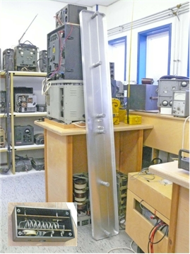
Fig. 18: Dipole for reception 38 MHz signals (measures according the manual)
A limited but annoying problem was experienced related to the initial batch of symmetric cable (brown) from an unknown origin, other than manufactured in the early 1940th. At testing the antenna assembly, no signal was transferred. Close examination of the cable showed a greenish discoloration of the foam dielectric, identifying that the cable had possibly been emerged and that moisture and copper-oxide had ruined the dielectric properties. An alternative symmetric low capacitance cable (blue) was successful applied.
Supply and conversion of power
Resistor Network or Widerstandkasten
As stated earlier the complete FuBl 2 is self contained but is supplied from the aircraft’s
24 V on-board battery. The battery itself is not connected to the chassis. A symmetric chassis or ground connection is provided by placing two power resistors (Widerstandkasten, Fig.3) over the battery and grounding the middle connection.
No power is drawn from any circuit over this connection. Capacitive decoupling is provided locally in the circuits.
U8 rotary converter and stabilised high voltage power supply. ( Fig. 3)
The anode voltage is derived from a rotary converter supplied from the on-board battery. The output of the converter is stabilised by applying the output through a baretter for constant current and to a gas filled stabilisation tube for constant voltage of 210 V, with-in +/-2Volt. (See Fig. 19 for an internal view.)

Fig. 19: Stabiliser of the U8 output voltage
The U8 is switched on and off by a pilot voltage to the internal power relay.
Some repair and maintenance was required to get the unit properly functioning.
Both sides of the converter are connected through rubber vibration dampers that are adhesive bonded or bonded by vulcanisation to the chassis hardware. One bond to the chassis opposite of the red cooling fan was defect. It was repaired by removing the converter, abrading the metal and rubber side of the bond and after careful cleaning and drying, the adhesive bond was restored by applying Sikaflex 252 polyurethane 1 component adhesive.
The adhesive was applied on both sides and left curing for 1 week, after mating the surfaces.
In addition, both ball bearings were washed and a ball bearing grease applied sparingly. This involved removing the rotary converter from the assembly and disengaging mechanically all vibration dampers.
The bearings could be accessed by removing covers, although it also involved removing the fan. (Fig. 20 )

Fig. 20: Rotary converter assembly
The relay contacts showed to be discontinues and had to be cleaned or polished.
The high and low voltage collectors on the armature were not touched, and the carbon brushes were not replaced.
The unit performed full with-in expectations for many hours experimenting with the FU BL 2 system.
Equipment used for alignment and simulation.
During the initial assembly, “failure analysis” and alignment phase, a Rhode & Schwartz programmable signal generator SMS 2 has been used.
The 24 volt was initially supplied by a stabilised mains power supply. The high voltage was also supplied by a electron-tube stabilised supply.
For final functional verification and demonstration, the 24V has been taken from a lead acid accumulator and the U8 rotary transformer and stabiliser supplied the high voltage.
For simulation of the AFF signal and simulation of the respective VEZ and HEZ signals
the platform “Prüfsender” PSU 0 B has been applied. For simulation of the keyed AFF signal, a relay switching arrangement was added as a” piggy bag” to the high frequency or antenna output.
A Note Book memory scope PCSU200 (Velleman Instruments) has been applied for recording the wave form outputs from the EBl 2 to the AFN1 indicator.
As stated earlier no keying has been applied to the VEZ and HEZ signals.
Table1. EBl 3F, channel frequencies per remote control unit FBG 2
Note 1: This Channel versus Frequency list is specific for the EBl 3 F.
See further the text. No radio channel is allocated to Tab 34.
The frequency 33, 200 MHz is for mechanical reasons not available
Table1. EBl 3F, channel frequencies per remote control unit FBG 2
Note 1: This Channel versus Frequency list is specific for the EBl 3 F.
See further the text. No radio channel is allocated to Tab 34.
The frequency 33, 200 MHz is for mechanical reasons not available
Table1. EBL 3F, channel frequencies per remote control unit FBG 2
Note 1: This Channel versus Frequency list is specific for the EBL3 F. See further the text. No radio channel is allocated to Tab 34.The frequency 33, 200 MHz is for mechanical reasons not available

Hans Goulooze's contribution in PDF
By Hans Goulooze
Edited by Arthur O. Bauer
![]()