
Berlin FuG 224
Feld II
'Ersatz'
The conclusion of our Berlin FuG 224 Feld II substitute
Status: 21 December 2016
Let us go back to the foregoing webpage, where we have introduced an Acryl frame, constituting my future 'Feld II Ersatz'
We were waiting for someone who is capable, and willing, to help us finishing this intriguing endeavour.
As to keep it a beautiful device, great care has to be taken as to prevent scratches or that damages.
On Tuesday 20 December we finally could meet in Leiden and we quite instantly started discussing as to how this should be accomplished.

The first step was planning for witch part should be mounted where and how this should be done
The white sticky foil is to prevent for scratches and allowing for making preliminary notations.

The next step is pulling off the lower side foil

Followed by mounting the Acryl stand-offs
Their blue colour is due to the protection foils

My next move, is to mount the transmitter base plate

First pulling off the corner foil slightly and fixing the base plate against the frame
Viewing it from the rear side.
Next the ventilator being mounted

Followed by the especially 'invented' mounting for the LG 76 T/R tube, in England also known as Soft-Sutton tube
Viewing the setting from the rear side.
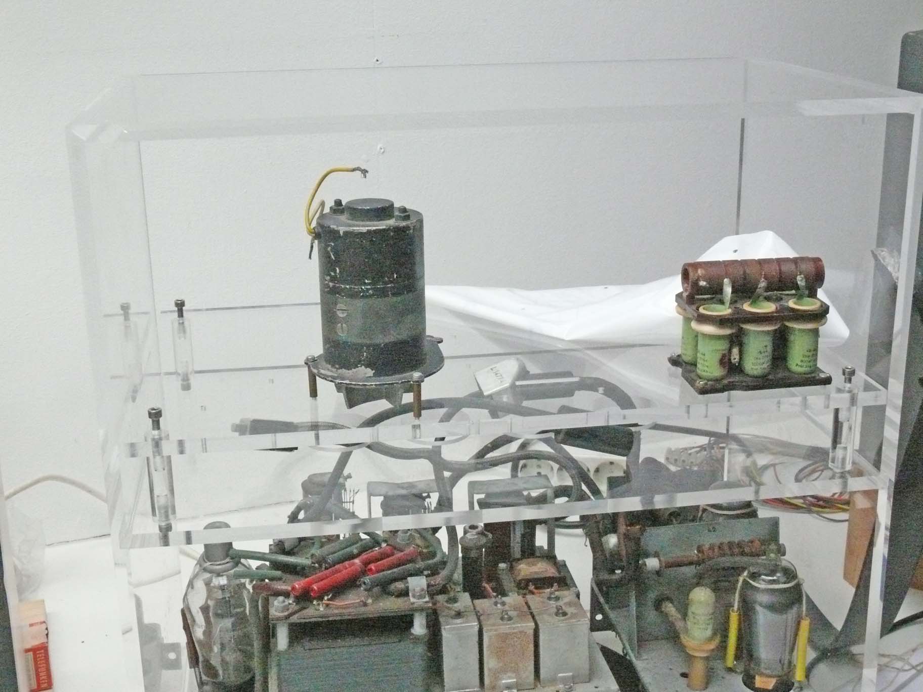
Because we are lacking all SHF gear, we have to be 'a bit creative' as to display the LG 76 tube transparently.
In between the ventilator motor and the pulse-forming delay-line we see the toroid HT pulse-transformer.
Please notice:- we display the various component about their once genuine position. Albeit, that the pulse transformer and delay-line assembly once must have been kept quite cramp within its sealed-off oil box; oil being used for insulation.

The far left-hand rear side:- looking at the box filled with so-called transformer-oil

The components available being mounted
Asking myself: is this what it should look like?
YES, entirely.
No mistakes?
Yes, only a small design error, albeit, a rather minor one.

Maybe not well visible, the so-called attached 'getter-bulb' is pointing towards the front, whilst we planned for just letting point it rearwards
Why haven't we done it this way?
When Jos and I planned the to be mounted bits and pieces, I forgot the shape of the HT pulse-transformer.
Why was this important, the only reason is:- that when the magnetron LSM 10 being rotated around its axis, the printed LMS 10 type number would become visible.
For it all should be demounted and I have to return to Jos Disselhorst in Leiden again. It isn't worth it.
Please bear in mind, that the visible connectors are to be kept underneath the Acrylic base plate.

With some imagination you can see where some of the cables genuinely had been connected onto The small connector being fit underneath the transmitter bottom plate on the right-hand side; whilst the heavier connector is fit on the far left-hand side next to the 'trigitron' (spark) tube type LG 201
Not visible here are the single HT cables, as well as the spark-tube-trigger-cable.

Rotating the Feld II frame anti-clockwise
In front the 'spark' tube type LG 201, left of it looking at the delay-line; on the right-hand side the single phase rectifier diode type RG 62D.

Viewing from the left-hand side front corner

Why not viewing it from the opposite side?

Now from the full right-hand side
Isn't it beautiful?

Viewing our Ersatz Feld II from the the entire front section

In my perception is this 'Artistic Substitute' of Feld II better than trying to reconstruct a frame from which we are lacking details
Viewing our frame from the rear side.

Viewing our Berlin FuG 224 set up full-face, as it normally is displayed
Please remember:- we have brought on display all bits and pieces we possess.
Quite some parts have been stored in a box for more than 38 years!
Once I called it my 'poor man's' solution.
But really poor it isn't!
By Arthur O. Bauer
![]()