
Continuing Nachtfee aircraft display reconstruction with:
Chapter 18
Chapter 19 (9 September 2022)
Chapter 20 (12 September 2022)
Chapter 21 (8 October 2022)
Chapter 22
This page was, for technical reasons, initiated on 4 September 2022
Current status: 8 October 2022
Photo 1: During the summer holidays Hans Goulooze commenced a fine job constructing the stabilised HT power supply which was integrated onto the existing wooden system plate

Photo 2: A quite nice view on the way Hans Goulooze did built-up the various components
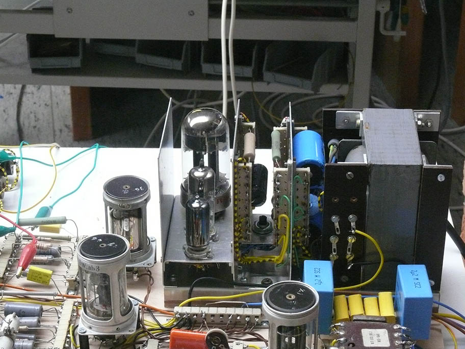
Photo 3: Viewing it from a slightly different perspective

Photo 5: Considering it from the opposite (top) site

Photo 6: Considering it, from what later will constitute the upper side perspective
Photo 8: Here the circuit plate (board) has to be mounted

Photo 9: Hans is determining the position of the bottom wooden sliding-rail
Our concern mainly is, that the board should be easily mounted and demounted by a single person.

Photo 10: The sliding rail being filled-up by means of a wooden strip as to ease correct horizontal mounting
(19) (9 September 2022)

Adjusting the two nuts against one-another as to allow smooth turning of the common screw-threat; as the centre screw has to be kept when the mounting-plate being detached from the current mounting
Please, imagine: that the two nuts, each one pressed in their wooden frames.
The Challenge to assure that both srew-nuts being positioned against one another that the screw rotates through up to the (stress) fixing point
The colours of the connections correspond with the colours of the according jacks.

For this moment we have waited about a year
(current consumption of 1A is telling us that only the new circuitry being operated; 25.1 V constitutes our substitute aircraft battery supply (Bordspannung).
Of course, it all is a reconstruction of the kind of display once used in, with Nachtfee, equipped aircraft.
However, the developed circuitry was engendered in step-by-step process.
Our line of thought: using, when appropriate wartime German valves en techniques then known.
Some adaptations were necessary, because we lacked some essential dust-core components, and we had to utilise existing transformers instead.
However, our advantage it was a thrilling process which resulted in a success.
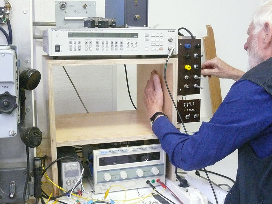
The only essential difference compared to wartime techniques - is the application of a Philips/Fluke PM 5193 synthesizer.
That we use this versatile instrument originates from our early learning days after our Nachtfee Consol arrived on 12 November 2011.
The stability of the internal quartz crystal was so poor, that it wasn't even possible to keep the time-base more or less stable for 5 à 10 seconds!
For it, we implemented, successfully a Rb-frequency standard allowing now values of: 10-10 and 10-11. Even the PM 5193 at 15 kHz isn't stable enough, only because we operate it at 500 Hz, thus divided by a factor of 30; making it sufficient stable. During the wartime days, the displacement of a Ju 88S was about 600 km/h (166,6 m/s) and therefore necessitating constant distance re-adjustments.

In someway or another this line drawing must show how once the aircraft Nachtfee display must have looked like
This information was derived after interrogation of German personnel.
You may now better understand why we have constructed it the way we did; please forget the two controls for focus and brightness, which we have, for practical reasons, positioned above- instead of below the CRT display.

On the far left-hand side the FuG 25a transponder
down in the centre two interfaces.
The left-hand one converts the IFF (or EGON) necessary for painting the Nachtfee order signal at the LB2 CRT.
The right-hand interface is just operating in the opposite direction, as it feeds the aircraft time-base 0° signal towards the Nachtfee Consol on the ground.

This photo is quite self-explaining
This is the actual reason why we had to mount the circuit plate the way we did.
On the right we notice the staircase entrance to our basement.
The basement facilitate: a workshop and valves storage including various bits and pieces.
(20) (12 September 2022)
YouTube film impressions
Film 00116: I am pointing at the far right-hand side on the HT power-supply providing 2.5 kV, of which is, actually, remaining 2 kV at the deflection cylinder of the circular LB 2 crt (due to the application of zener diodes). Hans Goulooze created, during summer time, a soundly constructed stabilised HT power-supply, which facilitates ca. 280 V. For it we adapted, for practical reasons, post-war valve types. The system concept, like in wartime days, relies also upon the 24/25 V dc "Bordspannung" which historically also obeyed to multiples of n x 6.3 V. Between the cathode of the series regulator valve and its according filament we measure, ca 280 V difference. Far too much voltage and the normal solution is, to employ an additional, insulated towards ground, filament transformer windings. Also the used EF 80, as its cathode lays here at + 90 V against ground; thus an extra separated filament transformer winding is necessary. The matching 220 V (230) transformer was at hand (Hans Goulooze's gift) and we therefore did it this way.
Film 00119: Is showing the results of just over a year lasting commitments, in (re)constructing a LB 2 circular crt display with all the background technologies. Not claiming that it once did look like this; but at least we know that they operated a LB 2 circular crt - like is maintained in our Nachtfee Console as a 'control screen'. We encountered, already from the beginning (hysteresis) that distortion of the to be operated 'sine and cosine' signals necessary for the two deflection Yokes systems, were limiting the projection of a soundly painted 'circle' at the LB 2 screen. Theoretically, there is no way around to compensate these kind of distortions. Again a brain wave - why not tuning each deflection Yoke section in 'series resonance'? Some of you might remember - that distortion is being caused by the existence of some kind of harmonics - odd or even or combinations. By tuning the deflection-coils in series resonance (all systems are relying on sine-wave signals), we eliminate to a great extent the amount of harmonics. And it truly works! The advantage is that due to the implementation of a series capacitor that we were able to implement (inject) a small (variable) dc current (ca. 3 mA) by which means we can adjust the circle inside the engraved markers. Not understood then (2011 .. 2012/2013), was that the Nachtfee system could only be operated when there is a second system-timing reference available. I came - after a quite long process of various, imaginable, considerations - to the conclusion that the 0° phase air-system pulse had to be supplemented to the existing signal chain (aircraft - ground station, vice versa). About 2016 someone most kindly - she managed to pass onto me a copy of the report made in June - September/October, 1945, in New York. Life would have been quite more easy wouldn't they (US Navy) being so '...' (not interested) to publish (September/October 1945) the description of the aircraft display schematically, at a level of: C14 is connected on to R17 ... Finishing with noticing that the schematic was no-longer is existing. (They lost it within 3 months!) Therefore, we ourselves had to re-invent everything! Nevertheless, this document: Technical Report No. 520-45 October 1945 (kept at NARA); at least it was confirming that my own considerations were correct - that a timing reference pulse (signal) was additionally added towards the ground sent via the FuG 25a transponder as well. This additional timing information allows the system to adjust the signal phase such - that it is being displayed at the LB 2 crt screen inside the 'pathfinder' aircraft just in time (correctly).
Film 00120x: (AOB: 'x' only indicates that about the last film minute had been deleted) Viewing now the Nachtfee Console 'on the ground' again, operating within the current (re)constructed LB 2 display. Shown is also - that Nachtfee basically relies upon a coherent system, where the main timing signal parameters originating from a single signal source, whatever their phase difference is, like additionally between the ground station via the aircraft transponder arriving again at the video-input of the Nachtfee Console. The aircraft time-base reference signal shown at the Nachtfee control screen, have to be constantly adapted to the actual separating distance between the ground-station and the pathfinder aircraft (the German pathfinder aircraft type Ju88S could have displaced itself with about 166.6 m/s max.) and demanded constant ground consideration. Because both systems relied upon comparison between both 0° instances of the - Nachtfee Console as well as the aircraft time-base source - we can now take only into account the common 0° situation displayed on the Nachtfee Control LB 2 screen (please notice: that the signal distance upwards is (approx.) equal to the signal displacement downwards). Generally the aircraft 0° phase pulse is adjusted also at about 0°; because there are some minor time-delays due to the electronic circuitries and minor deviations had to be systematically taken into account. One thing can be proved, is, that adjusting precisely at a given fixed 0° point, it is ascertained that the order signal vector equals the given order at both screens - in casu - on the Nachtfee Console as well as at the aircraft LB 2 screen. Please bear in mind: that 500 Hz prf constitutes a range of 600 km; in radar terms, the signal has to pass the trajectory twice (up - down), the radar range becomes: 300 km.
(21) (8 October 2022)

Today Hans first considered: to increase the performances of the two interfaces (in front centre left)
One aim was to eliminate a phantom pulse quasi linked with the time-base reference pulse; from which the sine- and cosine signals being derived. The interface module down right is also fed from the PM 5193 synthesiser as well as connected in two-ways with the FuG 25a transponder. It responds just after the sine wave signal passed 0°; of course, with a few µs delay. This pulse is sent towards the ground station and being used there as to provide a reference signal which is derived from the display time-base in the aircraft.
Without this essential reference signal - the Nachtfee system cannot operate.
What has to be known in the ground station, is, the actual distance between the ground station and the to be guided aircraft. Fore it - the most simple way is to consider the ground signal returning via the aircraft transponder and arriving again at the ground system.
When now the returning signal visible on the LB 2 circular crt is adjusted such that the transmitted and returned signal are pointing at the same 'compass vector' then the LB2 time-base delay has compensated for the distance (range) between both stations.

The circular LB 2 control screen is showing two signals
Let us consider the pulse pointing at south: notice the small pointer facing south.
Please consider now - the control left of the Command-Compass; its setting is adjusted at ca. 240 km; thus the LB 2 time-base delay (= the transit-time vice versa the ground station and the aircraft in relation to the velocity of light) is now correctly adjusted.
However, we still lack complete information about the actual 'phase status' of the time-base in the aircraft.
This information is essential as to regulate the correct time of arrival of the Nachtfee Command signal.
Fore it the Phase control has to be manipulated such that at least the arriving signal, considered in the phase domain arrives just in time so that the rotating crt spot reached exactly, in our case, at the 180 (south) instant.
On the ground, the correlation between the ground signal passes through the aircraft transponder and the time (phase) difference between the instance of the aircraft time-base 0° pulse which is injected at the same signal point as the ground signal being received. What you want, is, that the 0° aircraft time-base signal and the returning Nachtfee signal becoming in phase (time) in line, with the LB2 control-screen time-base.
When distance being compensated correctly, such as here for ca. 240 km - then the transmitted signal phase returning via the aircraft transponder is just received such - that transmitted command (actually here a 180° phase delay) for a Command Pauke (or call it south).
But compensation should be managed such: that the returning time-base reference signal arrives at 0° at the Nachtfee control screen. Theoretically this is correct but some delay in the aircraft electronics has to be compensated for. This maybe considered having a constant value.
Please consider now the LB2 screen again.
You notice the the pulse a few degrees passing North or 0°(caused by delays due to delays in various electronics), this is found to be the correct phase compensation value (thus: the aircraft time-base pulse should always to be adjust a few minutes passing 0° caused mainly by the electronics in the simulated aircraft.
Already often demonstrated, but I would like to explain it again briefly.
Please consider the Nachtfee control panel: The 'Phase control' down left is controlling a rotating phase phase-shifter between 0° and 360°.
Nachtfee, like most old radars were coherent systems.
Where the returning signal always is in coherence regarding distance (phase shift) and system time base; the reason both - the transmitted pulse and the time-base being derived from the same generator source.
But, the Nachtfee aircraft system is providing its own time-base signal; and therefore is not 'coherent' in regard to the ground station.
Now a phenomenon, often demonstrated: the returning Nachtfee signal pointing at south (180°) is coherent and will not respond upon phase delays caused by its own Phase control, but: it causes a phase-delay (instant) of arrival on the aircraft display!
Now the praxis: the signal painted pointing just passing North (0°) will move around the circular time-base on our LB 2 Nachtfee control screen. Though when it is being adjusted - as is visible here - then it is ascertained that the instant of arrival at the aircraft crt screen is equal to what has been sent upwards to the aircraft system.

Please neglect my incorrectness and control mistakes
It is thus evident - that the aircraft time-base reference pulse has to be adjusted about a few minutes past 0 degrees.

The interface on the right-hand side got a clamping diode (RV12P2000 wired as a diode) parallel onto its output signal, as to eliminate the negative going pulses

The advantage of this clamping diode as well as another modification is, that we got rid of a ghost (phantom) pulse following the time-base reference signal, about due north
please notice: that the time-base rotates anti-clockwise

Viewing a signal originating from one of the interfaces as well as the according LB 2 video signals

Viewing the right-hand side of the Nachtfee aircraft rig
Two provision have been made by Hans to guide the various cables
Who could have predicted the current outcome of our endeavour which did start in early September 2021?

Most of you will agree that we really have achieved something, within just over a single year
(22) ( )

We have modified this interface with a clamping diode RV12P2000 wired as a diode; meant for clamping the positive output pulse against ground, as the following video interface does need this

The small value remaining being cause by the space-charge between the cathode and the rest of the electrodes (in the long past also known as 'Edison' effect; a phenomenon he encountered it first in the world
From some reactions I understood that not all our YouTube film are passing on sufficient understanding of what it all is about; I therefore have decided to add some additional data and films onto this website.
Maybe it is advisable that some of you take first some notice of a lecture I presented - in September 2020:
https://www.cdvandt.org/Nachtfee-V6.mp4
Most system information is provided between: ca. 58th minute and ca. 1:22 (1 hour 22 minutes)
The film starts with the history how we obtained it in November 2011; followed by the technical survey necessary to recover its principles; which process took me > 5 à 6 years (+), before I really was fully able to grasp the theoretical context, myself.
Arthur O. Bauer
YouTube films:
Film 00126: Viewing the control-panel of our Nachtfee Console; in particular the 'Control/Order Compass' and the circular LB 2 crt. We haven't dealt with the additional EGON guiding signal for a long time. Egon was an essential navigational aid, based upon Freya technology; though now operating as a secondary radar system (signal not bouncing at a metal surface as normally radar signals do), but being retransmitted by means of a sensitive receiver and retransmitted by means of a quite power-full sender and received by the EGON system again. Due to this means - the range increases beyond 300 km. The time delay between the transmitted and its re-reception on the ground again contained information of distance as well as aircraft recognition; also known as IFF - Identification Friend or Foe) However, the transmitted pulse being received by the aircraft transponder (type 25a) and is returning towards the ground station. Its prf differs here between 1 or 2 Hz only (genuinely 2, 4, 6, 8, 10 Hz at a particular demand), but does not interfere with the coherent Nachtfee signals at all; as Nachtfee stays stationary (for some time) whereas the Egon signal blip rotates visible without visibly interfering. Demonstrated also is: that the arriving time-base reference pulse arriving from the, virtually, guided Nachtfee aircraft (blip shown towards north) can be moved around the time-line, - whereas the Nachtfee pulse, which returned via the simulated aircraft transponder, doesn't move (or minimally due to some goniometer errors) because it behaves inside its system coherent. This time-base reference pulse being generated inside an interface in the simulated aircraft: that the shortly after the time-base sine-wave signal passes 0° a few µs thereafter - produces a pulse which we consider being the aircraft reference pulse. Theoretically it should be adjusted also at 0°, but delays in the accomplished electronics has to be compensated for as well. Not explained: but also the Nachtfee signal passes with some delay through the various electronic circuitries, but this value will be compensated for by means of the range compensation scale - visible up left of the Order Compass. Easily: albeit there exists another means, simply consider:- the order pulse set at the Order Compass by means of the small pointer, - adjust now the range control scale such - that the circular LB 2 control screen paints at the same screen vector the returning Nachtfee signal blip.
Film 00127: Again the Egon signal pulse being visible, but is in no way interfering with the Navigational means of the Nachtfee system. The Egon signal (prf) differs only a single Hertz and is nevertheless not interfering with the Nachtfee system. Explaining the purpose of EGON as a necessary control the pathfinder towards the area were it had to drop their flares.
Film 00129: We now consider the simulated, newly constructed, aircraft display. Viewing the EGON guiding (rotating) signal blip, albeit - that this actual system did not concerned Nachtfee directly, though was maintained for navigating the aircraft towards the area where the flares had to be dropped over the target. The EGON signal prf differs only a single Hertz from the actual Nachtfee prf. But, the Nachtfee signals behaving in coherence within the Nachtfee system; as long as it is being monitored on the Nachtfee Consol LB 2 control crt screen (actually shown). That we still have to readjust sometimes is being cause that the simulated aircraft display (time-base signal) is derived from the Philips/Fluke PM 5193 synthesizer, thus is being based upon a quartz crystal; whereas our Nachtfee Console being based upon a Rb-standard, thus on some kind of atomic resonance.
To be continued in due course
By Arthur O. Bauer
![]()