
On 24 December 2022,
with the support of Paul's and Marc's muscle power,
we have started to reshuffle
our Exhibition space again;
after a
more than three years lasting pause.
Current status: 14 February 2023
Chapter 2 (13 January 2023)
Chapter 2a
Chapter 3 (26 January 2023)
Chapter 4 (since 14 February 2023)
Let us first take a quick and brief view:
Most artefacts are returning at their regular places since many years again, but we also would like to display new artefacts;
from right to the left hand-side we notice:
The Radione station R3 and RS 20M both in their genuine suitcase; and being interconnected by mean their genuine cables.
https://www.cdvandt.org/exh-det-36a-radione-r3.htm
Notice also the YouTube film
Shown, from left to right: the Siemens R IV receiver, once the standard RX (Receivers) operated at the main Abwehr wireless base-stations.
https://www.cdvandt.org/RIV-Handbuchkopie.pdf
This receiver is on loan from Antoon Steenbakkers, whom kindly gave it on loan to us, after Hans Goulooze had accomplished the extensive R IV receiver restoration.
The empty square (left of the Lautsprechgerät) in its upper-plate-cover gives access to a changeable coil box; but differently than the HRO types.
The two suitcases constitutes a complete Radione W/T station.

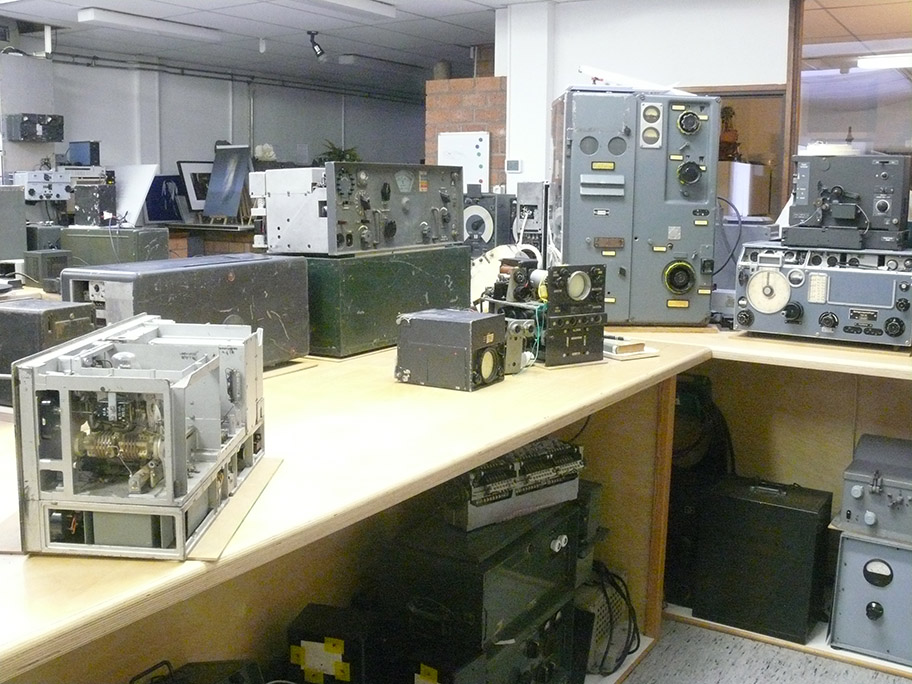
The exhibits being placed about their regular spaces

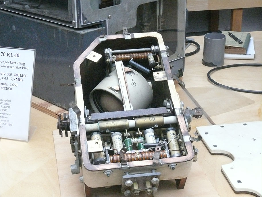
The Lo 70 KL 40 station returned at its former place again; although, the power supply (on the right of it) and the RX/TX have not yet been interconnected electrically on the left-hand side

The intercept receivers being back on the regular place.

At least I have been able to unwrap the various bits and pieces (components), but not yet been able to reshuffle and arrange them in groups together

The set in front is our 100 WS; below a genuine post-war power supply once manufactured by a German firm, but had been ordered on behalf of the Norwegian "Heim Verteidigung"
On it, just fit together the actual 100 WS; on to the genuine dummy-load, in our case connected onto the "Dachantenne" provision.
https://www.cdvandt.org/L-Dv-702-1-Heft-152-100WS.pdf

From left to the right: the 20 WS-c (covers also the 10 m band); on top of it the MWE-c* actually matching to the big 80 WS on the right-hand side of it
* Technically a beautifully constructed, high performance, receiver, including a tuneable quartz-filter and quartz controlled BFO.
Its frequency range fit exactly to the 80 WS-a and its smaller brother the WS 30a
On top of the MWE-c, we notice the Funksprech-f; on top of it its loudspeaker driven, occasionally, by the transmitter valve when being on reception.
On top of the 80 WS we notice the UKW-Ed1 RX
Right of this we notice the dual mounting frame with below the 10 WS-c and above it the UKW-e RX
Far on top we get an impression of the inside construction of the 10 WS-c
It all looks a bit stacked together now; the reason is: that we have less space available, due to the power supply to our extensive GKIIIb telephone scrambler system set-up (please notice the next two photographs)
(Noch Umbauen, wechseln MWE-c und UKW-Ed1)

Viewing the right-hand side of our integral telephone-scrambler system
The dark box constitutes the telephone-scrambler GK IIIb
The big grey box left of it constitutes the Tfb-2 (11 kHz) carrier-telephony unit
https://www.cdvandt.org/gk_iiib-operating.htm
and
https://www.cdvandt.org/exh-det-display-secr-comms-3.htm

Viewing the left-hand side of our integral German wartime telephone scrambler system
The dark grey unit is the 'other end of the line' scrambler
Attached to it we notice a Dutch 1960 S-65 telephone, next a tone-generator by which means we can demonstrate the side-band inversion effect of the conveyed speech spectrum

On the far left-hand side the German Tonschreiber-b (tape-recorder) 1944
The lower box containing the power amplifier and ac generator, which is providing variable tape-speed provision for the capstan motor.

The Tonschreiber-b, with on the left-hand side the "Zubehörkiste" containing 10 tape-reel boxes; as well as tools and spare-parts for the expander-tape-head and that like

On the far left-hand side an example of the aircraft DF-receiver EZ6 and on the far right-hand side, in the dark box, our "Hypso-meter" for calibrating barometric devices, for example, in U-boats
https://www.cdvandt.org/exhibits-hypsometer.htm

One of our aims is to show and explaining what is inside an artefact (apparatus)
A beautiful example constitute the KWE-a and a bit less the LWE-a receiver types well noticing what is visible inside
The dark module just in front of the S-406-S with the grey housing is the ominous:
https://www.cdvandt.org/exh-details-42.htm
Which is causing me quite some headache, as we are lacking any kind of technical, and relevant, information.

Mounted on the circular rotable disk; we notice our Adapted Siemens K12 autopilot converted, it once was operated in the U-127 small (2 men) submarine types.
It is technically operational
This system had been adopted and adapted by the Kriegsmarine - particularly for service within the small U-127 submarines.
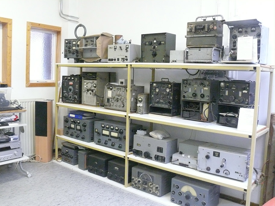
The second shelf from the top being re-arranged
From left to the right:
15 WS-b; Netz-Teil (power-supply) Ha5K39 - attached on the right-hand side with the Ha5K39 transceiver and just right of it the (small) dc-mains charger device
Torn-Fu-d2; AE 1020 receiver (is like a Torn Eb but with RV 2,4P700 and operated up to just over 15 MHz (a commercial receiver delivered, by Telefunken, to the Swedish Army)
Next to it the regular Torn Eb RX with its according battery box and incorporated HT-vibrator unit.
(2) (13 January 2023)

Our telephone corner is showing a variety of gear
It isn't easy to get artefacts replaced in its former environment again.

The two modules in the centre left- is the FuG 16 ZY receiver, on the right-hand side we notice the FuG 16 ZY system power supply NAPH
https://www.cdvandt.org/D-Luft-T-4069-FuG-16ZY.pdf + https://www.cdvandt.org/FuG16ZY-SB-E16ZY-A1.pdf

Albeit not planned for, apparently the focus upon our artefacts, this time, is showing what is actually visible inside some artefacts

From left to the far right-hand side: T9K39 (Main) receiver
Technically a rather complicated receiver with 3 stages RF pre-selection.
Next to it, the Telefunken transmitter AS 59, in the later 1970 my regular HAM transmitter. https://www.cdvandt.org/Tel-data-As59.pdf
Next to it the light-brown case containing the ca. 1915 Wave-meter test equipment: https://www.cdvandt.org/exh-details-41-kgw2c.htm
On top of it: the receiver plug-in module of a DMG 5K Michael decimetre-link system.
Right of it a Schwabenland RX: https://www.cdvandt.org/D-Luft-T-4415-Kurzwellenempf-Ln-21021.pdf + https://www.cdvandt.org/rm_7-8-1943.htm
+ https://www.cdvandt.org/exhibits-details_11f.htm
Right of the Schwabenland Rx we notice the Lo6K39c RX: https://www.cdvandt.org/exhibits-details-21.htm Especially interesting is the base-mounting frame, which is explained in the foregoing hyperlink
It, should be regarded a high-performing TRF (= Gradeaus) receiver concept maintaining a 6-gang-tuning capacitor!

Turning to the end of the rear display room: BZA-1, the Ju 88 bombing precision-aiming computer: https://www.cdvandt.org/exh-details-30-bza1.htm

For me, and I suppose also for the visitors very attractive, is its beautiful and sound construction, additionally its mint fashion
See for details the foregoing hyperlink.

The reconstruction of the Seehund auto-pilot steering system, constructed entirely with genuine components; once demounted from a real U-127 mini-submarine, in 1945
https://www.cdvandt.org/k12-anlage.htm + https://www.cdvandt.org/k12-laeuft-wieder.htm

This time - I would like to show in particular typical German die-casting constructions
Shown here is the die-cast frame of a 100 WS transmitter: https://www.cdvandt.org/images18/Exh-replacing-again-12'22-p6.jpg
https://www.cdvandt.org/L-Dv-702-1-Heft-152-100WS.pdf

In the centre a very interesting Lorenz frame construction, which may be considered being the nucleus of the German portable sets in the 1930s
It had been designed (by Lorenz) especially for an expedition in the Amazonas, in early 1930s.
It was considered so reliable and easy to maintain that a range of successors that been designed and was also known as: LSE 2/203: Its successors got military nomenclature: Torn Fu b ... k and that like.
The above set became known as: Torn Fu a; albeit that also a different designation was maintained.
Left of it: we notice the inside frame of a 20 WS-b; which was maintained especially for "sound-ranging" measurements; which requires sound performances caustically.

I have tried to magnify the photo, with poor results, maybe you recognise that the coils and tuning capacitors being gold plated! Good visible, albeit that this device me be considered ca. 90 years old!
Late Frans Driesens gave me this set about the end of the 1970s, and he told me that he bought it somewhere on a market in Spain.
I was able to take a better class photo series shown at: 2a
The oscillator unit of the submarine transmitter S-406S/36 https://www.cdvandt.org/Tel-data-S406S.pdf
The backbone 200 Watt short-wave transmitter, employed in most German submarines.
Its concept, a typical Telefunken construction: push-pull oscillator stage - followed by a so-called: Push-Push stage.
This second stage provided a push-pull input, whereas the two anodes being directly interconnected.
Its purpose being: such a stage generates only even-harmonics, but where a direct 1:1 is necessitated one valve of the push-push stage being blocked by a sufficient amount of negative voltage, and the stage provides now even harmonics; however, the blocked valve is performing now as a neutrodyne capacitor for the valve stage still acting as an amplifier.
Please, notice its solid ceramic housing which is being, inside, heavily coppered!
Tuning is accomplished by means of a so-called "short circuit" gonio-meter; the ball is visible inside the ceramic cylinder. The inside coil winding being heavily silver-deposited inside the ceramic cylinder.

KWE-a receiver visible what is inside:
https://www.cdvandt.org/nieuwe_pagina_1.htm + https://www.cdvandt.org/KWE-a.pdf + https://www.cdvandt.org/hell-pa0aob.htm
In my perception its qua mechanical- and electrical- concept the best built receiver before and in the WW II; leaving out that it operated with battery valves type 11 x RV 2P800.
When I remember well, the tuning capacitor counted 7 gang-sections of the "frequency linear (curve) tuning type".
Hardly, another manufacturer built ever such an excellent receiver concept, where all theoretical considerations (details) had been implemented. Think of: that all coil units (box) and circuitries being entirely connected onto ground at a single, defined, earth-connection!

Viewing it from a different perspective
The device marked QL 2, is a dual quartz providing 250.0 kHz and 251.8 kHZ, which constitute upper and lower side-band provisions.
Hartley expected, it possesses an additional AVC (AGC) amplifier section, which externally can, at will, be switched on- or off. Audio gain can also be controlled by means of the RF and/or audio gain adjustments.

Lorenz, high performance, long-wave HF/DF receiver type E-3
https://www.cdvandt.org/exhibits-details-11b.htm
+
https://www.cdvandt.org/D-Luft-T-4453-Boden-Peil-Empf-Fu-Peil-E-3.pdf
An exceptionally constructed receiver.

Again our telephone "corner" a bit more in detail
The black table telephone was often used in Head Quarters, and is being connected onto the "Klappenschrak" up the top shelf

The black flat table-telephone being wired onto connection 10 and was called upon by the next provision

The buzzer was operated from the inductor crank of the right-hand side FF 33 (Feldfernsprecher type 1933 )
Communication is possible with the telephone described in the foregoing photograph
Shown here a KWE-a HF/DF receiver; two of the vertical mast being place on the left- and right-hand side of our display.
Normally four of these "Adcock" mast being maintained, but we possess only two masts; once swobbed, in the late 1970s, in Denmark. It took more than 40 years of storage, before we were able to combine both the masts and the HF/DF rigs together.
The genuine gonio-meter unit, mounted on the right-hand side of this adapted KWE-a, is quite rare, I obtained it about early 1980s, in Italy.
The dark grey unit on top constitutes the genuine power-supply unit type NA 6.
(2a)
I would first like to shown you how the LSE 2/203 was looking from a photo Fritz Trenkle

Fritz Trenkle
This photo might show to us the "non-tropical" apparatus version, but mechanically it is quite similar as our tropical version.

The gold plated components like wires, coil-windings and the tuning capacitor constructions are well recognisable
Please bear in mind, that this set is about 90 years old, and had been stored before someone gave it to me in the late 1970s, quite some is looking still good.

Shown more more details: the various gold-plating are well visible

Viewing it slightly differently
The resistors and some capacitors being kept within glass-tubes as was quite usually in the late 1920s and early 1930s
Capacitor part 46 was made by Jahre
Most HF carrying wires were gold-coated as were all HF coils

The female connectors down on the left-hand side were meant for interconnecting onto the lower control panel

It is clear that gold-plates is a good technique soundly lasting in our case more than 90 years

The way wiring had later been managed was by Lorenz common practice

Also the application of Bakelite was apparently a quite common practice

Really astonishing the neat construction of the early 1930s

This type of switch was known as: Nockelschalter

The right-hand side gear-wheel is directly controlled by a control-knob at the front-panel
(3)

This time viewing towards the entrance of our museum
The bright glowing Jagdschloss transmitter valves type TS 41
On right-hand side just visible the main unit of the X-Gerät https://www.cdvandt.org/gema-x-geraet.htm

In front on the left-hand side: the Kreuzeck https://www.cdvandt.org/jagdschloss-kreuzeck.htm the Jagdschloss-, but also the Freya receiver module; the Gemse IFF receiver; TH OB 110a display used in the range-measuring O-Gerät https://www.cdvandt.org/exhibits-details-17.htm + https://www.cdvandt.org/exhibits-detais-17a.htm ; next the Jagdschloss wide-spectrum transmitter module https://www.cdvandt.org/jagdschloss-tx.htm

Hans Goulooze's corner
In the background the Russian "copy" of the Patin repeater compass; though the Russian version is still functioning well, in contrast to the wartime Patin compasses of which we may say that: of 100 samples 101 being defect!

The bigger yellow box is the Notsender 2 (NS 2) during the war adopted by the US and widely used for decades
Next to it, the quite flat box is the NS 4, which was worn on the breast of fighter pilots when crossing the North Sea.
https://www.cdvandt.org/exhibits-details-ns4-new-discovereries.htm
On the right of it EZS 2 old version

On the right-hand side the: Anflugsender AS 3 (https://www.cdvandt.org/exhibits-new-reshuffled.htm#13)

Simply another photo shot
(4) (Since 14 February 2023)
On 13 February I created a new photo series, but now from a more elevated position; providing a different experience

1. On the left-hand side we notice the PT X frame, constituting a complete FuG 10 (FuG X) W/T station
right of it the EZ 6 HF/DF rig; linked with a radio compass by means of a repeater
https://www.cdvandt.org/apz6.htm
and
right of it, in a wooden frame the "Blindlande-Anlage FuBl 3"
https://www.cdvandt.org/fubl_3f.htm

2. From left to the right: Funkhorch Empfänger b; FuHE-c; FuHE-d; ... e; ... f; ... v

3. From left to right: Siemens R IV receiver particularly supplied onto the Abwehr and related services. In the centre we notice the Radione transmitter type RS20M and on the right-hand side the Radione R3 receiver
https://www.cdvandt.org/exh-det-36a-radione-r3.htm

4. SFM T62d (Geheimschreiber) corner
https://www.cdvandt.org/g-schreiber-docs.htm
https://www.cdvandt.org/g-schreiber-problems.htm
https://www.cdvandt.org/g-schreib-youtube.htm
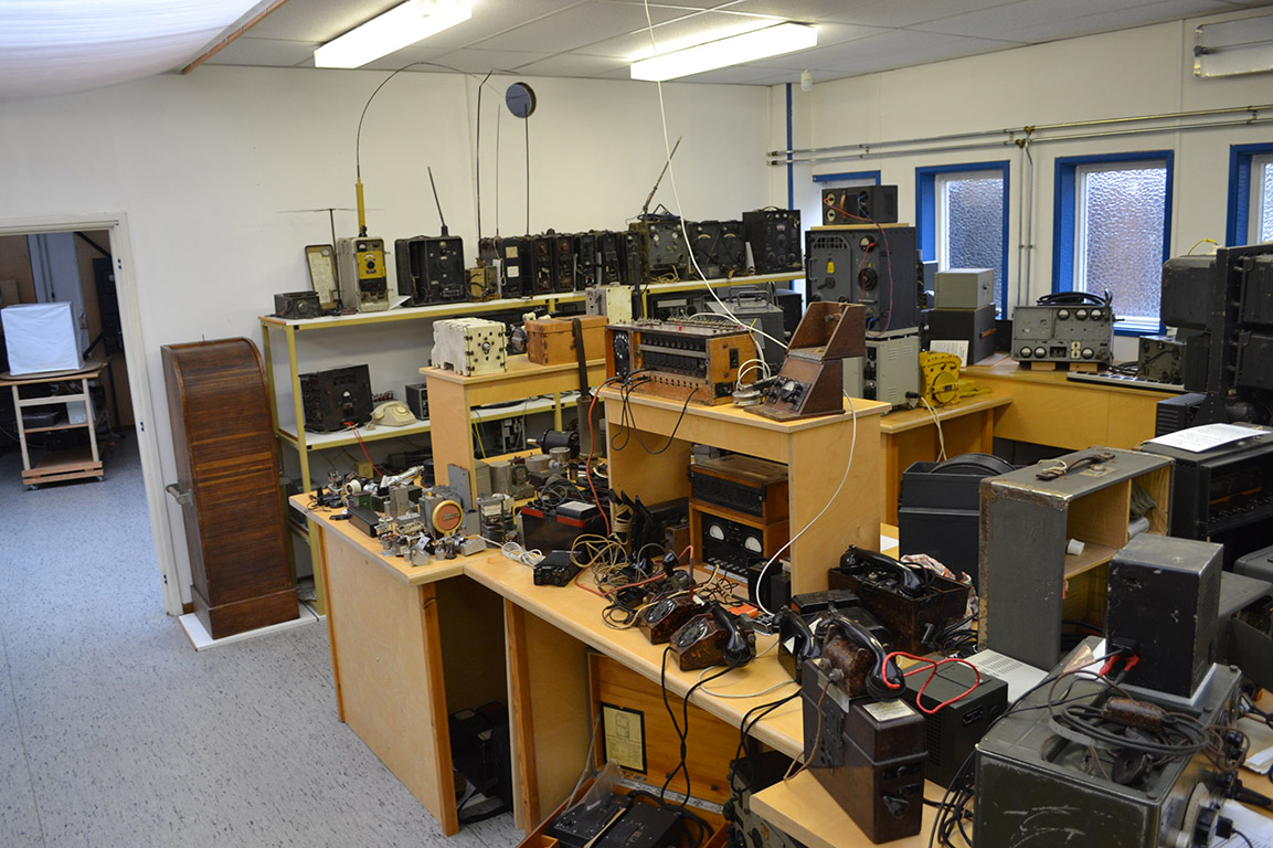
5. About the centre of this photograph, we encounter our telephone display, some are connected onto a small telephone exchange

7. On the left-hand side we just notice the S 406S Submarine transmitter (200 W); on the right we see the turret section of a KWE-a receiver

8. I myself admire the mechanical and electrical concept of the KWE-a receiver
In my perception the best concept possible. The only downside: the RV 2P800 battery valves, which in the days of its concept, say 1936/37, was an obligation on behalf of the German Army (WH)
as the receivers should fit to 2 V battery supply in the field. For instance: it maintained a 7 gang tuning capacitor!
https://www.cdvandt.org/exhibits-details-7.htm

9. Communications was the backbone of the German Military Services

10. Our GK IIIb system set-up.
It constitutes an entire scrambler - descrambler set-up consisting of on either line-end a GK IIIb "Sprach Invertierer" (speech inverter) in between a "carrier-telephony" system Tfb2 operating at 11 kHz.
https://www.cdvandt.org/gk-iiib-tfb2-demo-12-3'20.htm

11. In the background centre we see the 100 WS carrying on top the genuine artificial antenna dummyload

12. Korfu and Naxos corner In the far distance, we notice the Samos and Fanö receivers
https://www.cdvandt.org/korfu.htm
Naxos:
https://www.cdvandt.org/KL-FuMB-Tisch-0.jpg
+
https://www.cdvandt.org/naxos.htm

14. My Rarity Cabinet (Rariteitencabinet)
I love components as these tell us a lot about backgrounds and details

15. Lorenz E 3, a long-wave RX of very superb performance
https://www.cdvandt.org/exhibits-details-11b.htm

16. Viewing backwards: on the left our military telephone display section
at the far end the Funkhorch receivers

17. More or less in the centre we see reconstruction of (Seehund type 127) steering system, but the components being all genuine and originating from the mini-submarines once at the premises of the Dutch Hoogovens in IJmuiden (Ymuiden), about, say, June 1945

19. The three modules on the left-hand side belong to the Berlin radar exhibition, which was the result of capture near Rotterdam of the British H2S radar carrying serial number 5
https://www.cdvandt.org/agr_protocols.htm
and
https://www.cdvandt.org/manuals.htm
and
https://www.cdvandt.org/berlin-feld-ii-ersatz.htm
and
https://www.cdvandt.org/berlin-radar_survey.htm
On the right of it, we see the electrically complete Würzburg FuSE 62 Radar system
https://www.cdvandt.org/wurzburg_rep.htm
and
https://www.cdvandt.org/wurzburg_rep.htm#YouTube-films-88-96

21. Inside the acryl box we see the "Bordrechner" of a Ju88 aircraft
It was meant to aim a single bomb precisely at a target from an altitude of 250 m (minimally)
https://www.cdvandt.org/exh-details-30-bza1.htm
In the background we see our Lichtenstein SN2 reconstruction
Two two antennae below haven't been mounted as to prevent destruction by visitors.
https://www.cdvandt.org/SN%202%20antenna%20construction.pdf
https://www.cdvandt.org/li-sn2-connector.htm

23. In front the adopted Siemens K12 gyro controlled autopilot system, adapted for the application in conjunction with the Seehund Type 127 mini-submarine
https://www.cdvandt.org/k12-anlage.htm
https://www.cdvandt.org/k12-laeuft-wieder.htm

25. Second shelf left-hand side: Power supply to the Ha5K39a transceiver; FornFu-d2; commercial Telefunken AE 1020 receiver like a Torn E-b, but using RV 2,4P700 valves but operating up to about 15.3 MHz; on the far right-hand side a genuine Torn E-b receiver, both receivers being fit with their genuine battery boxes

26. In the centre, below the 20 WS-c; on top of it the superb receiver MWE-c; on top of the latter the Funksprech-f
on the right of it below the 80 WS-a and on top of it the UKW E-d1, a beautiful VHF receiver!
Right of it, quite rare the dual-mounting frame for tanks and that like. The MWE-c and the UKW E-e and 10 WS-c all possessing similar outside measures.
https://www.cdvandt.org/exhibits-details-20.htm

29. On the left the 100 WS mounted at a power supply once ordered by the Norwegian "Heimverteidigung" and supplying all necessary voltages as well is providing an exact mounting base

30. On the far left-hand side the so-called: "Hypsometer"; the black cylinder right of it, is the electro-mechanical sensor of a "Magnetic Mine" (beautifully constructed)
https://www.cdvandt.org/exhibits-hypsometer.htm
and
https://www.cdvandt.org/magnetic__det.htm

32. On the left hand side: the complete including its transport cases the WT 40 system, providing 6? telex (Fernschreib) channels over a single telephone line (think of speech telephone bandwidth)
https://www.cdvandt.org/exh-details-43-dmg-5k.htm

34. Viewing towards the entrance door; the two brightly glowing TS 41 valves belongs to the Eibsee transmitter providing ca 40 kW peak power onto the Jagdschloss system, with enhanced HT it could provide up to ca. 100 kW transmission pulses
https://www.cdvandt.org/jagdschloss.htm
https://www.cdvandt.org/jagdschloss-kreuzeck.htm
https://www.cdvandt.org/jagdschloss-tx.htm

39. Entering the first exhibition space

40. Again viewing our Abwehr related wireless station
On the far left the Siemens Type R IV reciever; which uses changeable coil-boxes and a tuning dial with numbers; but both being entirely reconstructed by Siemens.
Next to it, in the centre the Radione RS20M TX and on the right the R3 shortwave receiver.
Rare are the two genuine storage/transport suitcases.
https://www.cdvandt.org/exh-det-36a-radione-r3.htm
About 1946, PA 0 MM - OM Metselaar collected a wide range of quartz crystals in the range of the 80 m band and the 40 m band, spacing 5 kHz.

41. In front the Nachtfee Console; on top if it our Rb-frequency standard
https://www.cdvandt.org/nachtfee-airdisplay-right-hand-side-new.htm#22

47. Closing today with the heavy ceramic VFO housing of the S 406S transmitter; there existed inside our S 406S transmitter housing an equal module
Please notice the heavy ceramic housing, can you imagine that heavy copper had been deposited inside it?
Our aim is, generally speaking, to explain technologies broadly, and not displaying front-panels only, as we did, for practical reasons, today mainly!
To be continued in due course
Arthur O. Bauer
![]()