
Siemens & Halske Wellenmesser Type KGW 2c
Page initiated: 3 March 2022
Page published: 4 March 2022
Serial number 7670

The mahogany (?) box
Supposed year of its introduction about 1915
I understood first, due to the Telefunken label, that it concerned a Telefunken apparatus, but there is good reason to designate it as a Siemens & Halske product (notice 'S&H') on the foregoing type plate, up on the right side of the plate)
On the other hand, we have to be aware, that Telefunken was owned mutually by AEG as well as Siemens & Halske.
Thus both Companies were involved; on the other hand, Siemens & Halske had also their own products on the markets before the end of World War One.

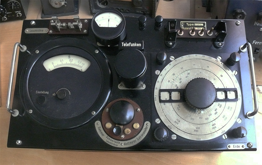
The main centre module being pulled out the box
On the right-hand side we notice the scale and its vernier-scale drive (down left annex the circular scale).
On the left-hand side, what I consider an meter indicator.

Now with plugged-in galvanometer
Some where in the centre the shape of a detector device
I cannot yet distinguish whether it concerned a "pyrite, or silicon, or other type of detector device. The Telefunken detector being plugged-in accordingly

The Telefunken detector being plugged-in accordingly

Hans Goulooze is holding the "Summer" (Buzzer signal source in his hand)
Of source, cover being removed
Its purpose was two-fold: modulating a signal as well as to causing some kind of interference
Summer (Buzzer) being plugged-in, accordingly

Siemens & Halske (S&H) Type K.G.W.2c
The connections were to be linked onto a selected coil

One of the coils being inserted directly ( top far right-hand side)

An early 20th century an interconnecting leather "flat-cable" being placed between the wave-meter and the external measuring/search coil
Hans Goulooze keeping both stable during the photograph.

Maybe explaining the situation

Leuchtröhre E.R.101
Leuchtröhre is a device that indicates when the fed onto it RF voltage exceeds say 90 volts
The side-effect is that the neon gas igniting is also acting as a voltage limiter; this indicating the existence of higher RF energy as well as, when ignited is limiting its energy value.

The glowing ignition process cane be watched through this quite small slit
This might indicate, that also early (preliminary) signs of ignition can be observed.

A sound photograph of the Summer / Buzzer device; which also served as a transmission signal source (weak signal source)

The battery compartment
The two batteries count be connected as to operate in parallel or in series.

Battery compartment opened

The main function selector switch

Viewing also the cover around the tuning capacitor

Circa:
Band I λ 300 m - 720 m = 1 MHz - 416 kHz
Band II λ 640 m - 1550 m = 460 kHz - 193 kHz
Band III λ 1400 m - 2300 m = 214 kHz - 93 kHz
Band IV λ 2900 m - 6750 m = 103 kHz - 44 kHz
Band V λ 6000 m - 14500 m = 103 kHz - 20 kHz
Curious is, that the 5 coils being maintained inside the main wave-meter, but were also accessible from outside when the centre unit being carried inside its main transport box and being the, on the left-hand side by a door on the left-hand side. However, when the (top) lid being closed, then the left-hand lid cannot be opened.

Inside the box-lid there is tiny compartment which keeps the to be plugged-in circular 'Galvanometer'
The latter device being inserted only when operating it accordingly.

The galvanometer being replaced in its transport compartment

The stored galvanometer being saved for storage and/or transport

The lock key to de-lock the box

Finally the right-hand side lock number 222
By Arthur O. Bauer
![]()