
Horst Beck's impressive collection
I have made a selection (impression) of photographs, which originate from both Horst Beck and myself (AOB)
In progress
State of affairs: 26 May 2008
We may regard this collection being one of the best in the world!
My personal feeling is, that his complete Mannheim FuMG64 installation is the very interesting device of his collection. We may consider also, that this device is the only complete one left!
The Mannheim radar was the most accurate tracking radar of the Germans during WW II, but also the most complicated system. Its accuracy equals that of the famous US radar type SCR584
Front view of Mannheim apparatus
The two vertical antennae left and right of the central antenna, belong to IFF system

Rear view of Mannheim FuMG64
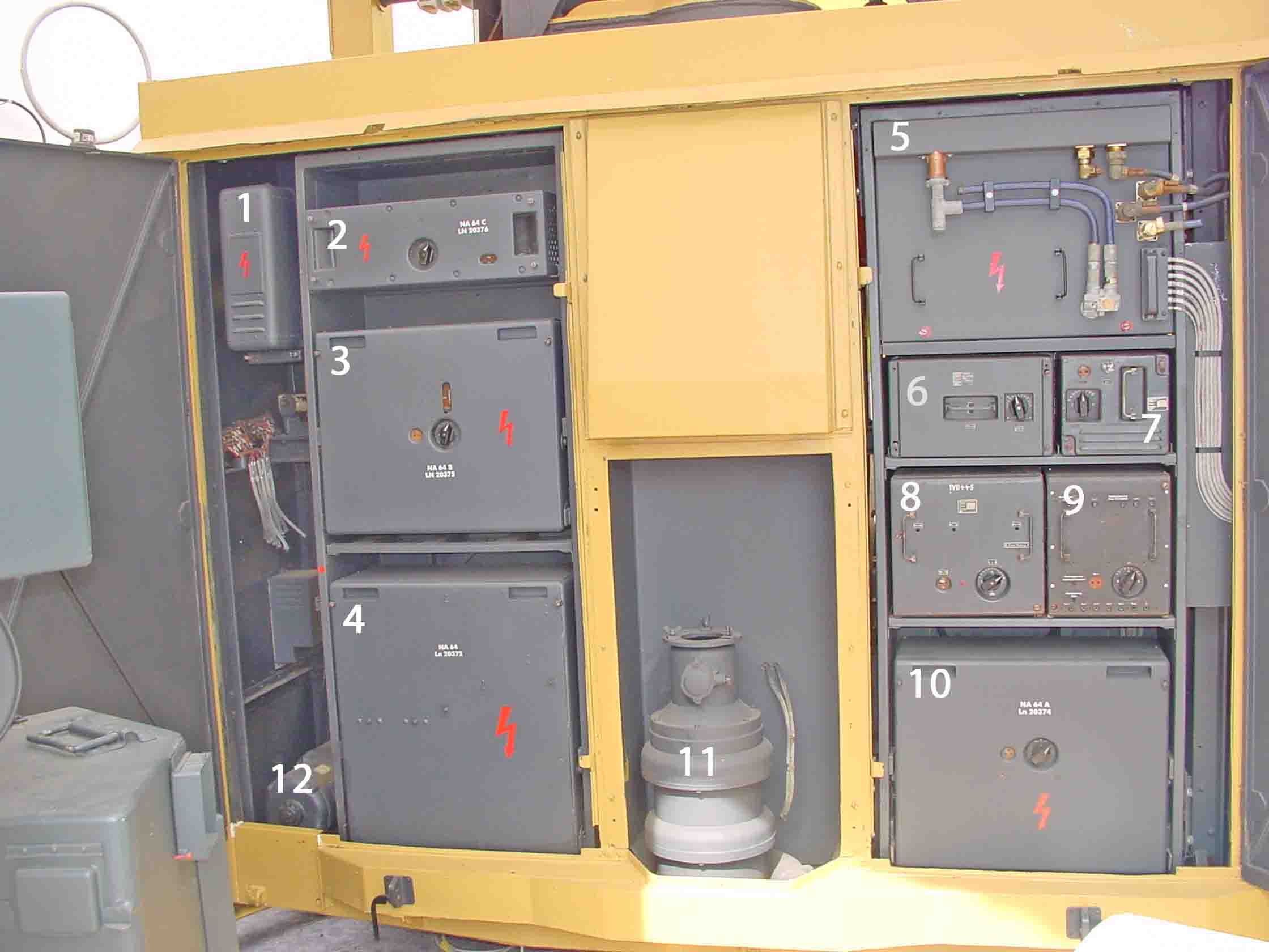
Let us continue with a view of its, impressive, instrumental compartment

The Germans call this: Geräteraum*
I would like to call it: operators cabine
1 Überwachungsgerät ÜWG, general radar display, which was controlled by the chief operator in charge (Geräteführer)
2 Peilanzeigegerät PAZ, this unit was to set (program) an azimuth sector, which should be constantly scanned (wobbling around a sector)
3 Anzeichegerät ANG, this display shows the overall (operative) range 0 - 40 km (similarly to ANG62 in Würzburg FuMG62 D)
4 Peilanzeigeröhre PAZ, this display shows only a magnified short range (segment)
5 Instrumental azimut-lay-off indicator. When a target was captured, this instrument shows, whether the target is too much left or right to boresight. Remember, that like Würzburg, both systems could accurately DF due to conical-scanning (Telefunken patent). Its rotating pencil-beam was de-focussed. Precise pointing was discerned when the target was exactly within the centre of 4 beam sectors (quadrants). (regard my book on this technique: Deckname Würzburg, please bear in mind, that opening this pdf takes 6.9 MB!)
6 Azimut-Steuerung, steering-wheel for azimuth. When the target was captured in the system, the azimut operator could manually kept locking on it. Both, azimuth and elevantion steering systems were electrical motor assisted
7 Entfernungsmessgerät EMG, the target range was transmitted to a repeater which was linked onto a predictor (Kommandogerät). The lay-off to centre, was indicated by means of a moving coil meter '8'. Settings were tuned by means of '16'
8 See previous
9 Höhensteuerung, elevation steering. See also explication '6'
10 Lay-off indicator for elevation tracking
11 Peilanzeigegerät PAZ Höhe, elevation control display, see '4'
12 Ek Rechengerät RG; Ek = Kartenentfernungsrechner, = mechanical computer, to calculate the actual point (position) of a target (projected) at a map. Looking from that point exactly vertically upwards, you would see the tracked target. This is being accomplished by means of a trigonometric calculation (sine and cosine), taking also in account the system elevation angle
13 Impulsgerät IG, low power pulse stage. Pulses were generated for all sorts of purposes, such as for: blocking, gating, synchronising, .....
14 Sicherungskasten, fuse-switches. The Germans used, in contrast to Allied practice, on a very wide scale 'switchable electrical fuses'. Nowadays, all over the world very well known
15 Bediengerät KG, I assume for controlling the associated IFF system
16 See '7'
17 Kontrollgerät, this panel indicated and controlled the various voltages (220 volt single phase and 380 volt three phase a.c. mains and also monitored the 50 Hz line frequency)
Next, we consider the various modules
First, the cabinets at the rear. For this occasion the antenna has to be elevated. As otherwise the two cabin doors (Gerätetüren) cannot be accessed
View on the two rear compartments
1 Pintsch-Regler, also known as: Netzspannungsregler 63 (FuMG 63 was radar type Mainz, which has much in common with Mannheim, which latter was actually its successor); carbon-pile regulator. Carbon rings were more or less pressed together as to control its resistance. Which causes a variable voltage drop. This was done such, that the voltage at the lower end was being kept constant. By this means, a.c. voltages could be stabilised. I don't know for Mannheim, but Würzburg used here 180 volt stabilised a.c.
2 NA64-C (NA=Netzanschlussgerät), power supply C
3 NA64-B, power supply B
4 NA64 or simply type 64, 8 kV Hochspannungsnetzgerät, 8 kV high voltage power supply for the transmitter
5 Kennungsgerät KG64/M2, IFF transmitter/receiver section. The open blue coaxial line (stub), belongs to the front-end T/R switching of IFF (Kuh-Gemse)
6 ZV Verstärker, intermediate amplifier
7 Verstärker Anzeigegerät VA, presentation amplifier module
8 ZV Verstärker OV, Amplifier to ??
9 Entfernungsmessbrücke EMG, e-value-measuring bridge (e = length of the hypotenuse)
10 NA64-A, power supply type A
11 Kühlgebläse mit Ölfilter, cooling van with oil impregnated air filter
12 Umformer Messwerteübertrager, rotary converter for data transfer

Left-hand side compartment
1 Entfernungsblende EFB, ECMM device, to blank or to cancel jamming interference
2 Mischteil, mixer section
3 Diodensperrteil (Ln20359), T/R diode-switch
4 Abgleichteil, its purpose is, to match transmitter and receiver T/R switch onto the antenna cable (Simultangerät)
5 Sendertastteil, anode power (pulse) modulator, with (modulator) valve RS300
6 Sendertastteil Stufe I, first pulse modulator stage
7 Sendertastteil Stufe II, second pulse modulator stage
8 Sender, transmitter consisting of two LS180s in push-pull, providing 16 kW antenna pulse-power (double the value of Würzburg, which had only a single ended 'LS180 PA stage')
Also impressive is his display on German aircraft radars

Flugzeug Radaranlagen 1942 - 1945
Beck's aircraft radar display 1942 - 1945*
This very illustrative display, shows from left to right (the red vertical lines separate the various systems):
Naxos FuG350Z and 350Zc; FuG212 (Lichtenstein c); FuMO61 (Kriegsmarine = Navy version of FuG200); FuG200 Hohentwiel; FuG220 SN2 (Lichtenstein SN2); FuG216-217-218; FuG202b/c and FuG214; Berlin FuG224. The black circular disk carries the Berlin antenna (array of 4 polyrods), below of it SG224 (PPI display), one shelf lower left a test gear for checking the LO parameters (Rd2Md/Rd2Md2), right of it the very rare receiver/transmitter module (magnetron type LMS10), very low the rather complex early antenna (drive) mechanism, which was replaced by an improved system (see Berlin discription/instruction), finally left of the antenna-module two 'Umformer' = rotary generators
Let us continue with another facet (section) of Beck's collection: Aircraft navigation and gyro-steering to: two- and three dimentional gyro-platforms. The display covers an entire wall and is too broad to get all at a single picture. Owing to this, I had to split the display in two pictures. There is, however, an overlap between photo 1 and 2*

Photograph 1 and 2 shows magnetic and gyro compass, gyro-platforms, wide range of cockpit instruments, Ward-Leonard generators/convertors, Rudermaschinen = electrical ruder-motors, Funkpeiltochter- Relaispeiltochter- Kompass, .....
Rocket guidance systems, for Hs293 and Fritz X (wireless and wire-linked) Displayed at the opposite wall
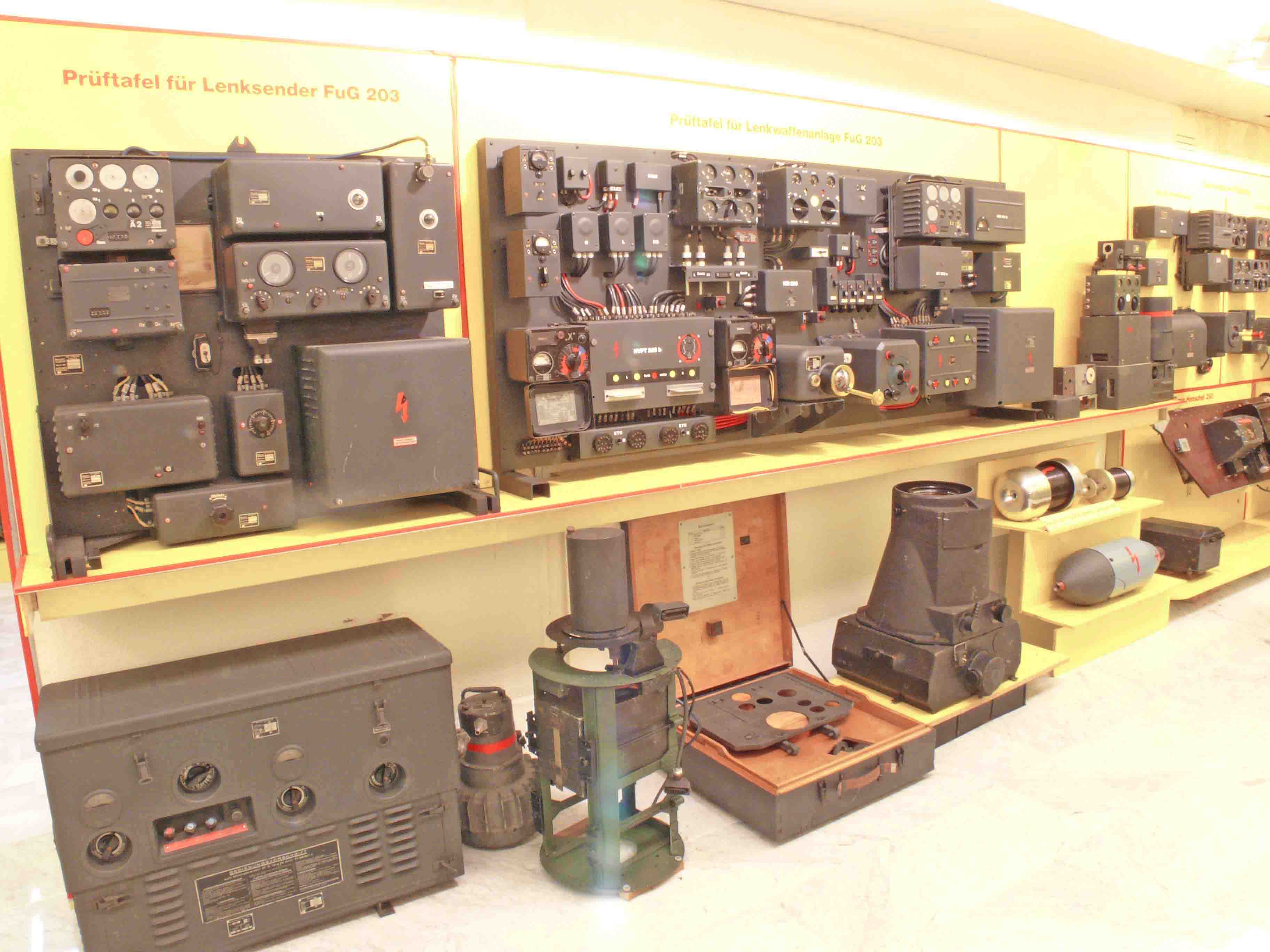
Prüftafel für Lenksender- and Püftafel für Lenkwaffenanlagen FuG203
Beginning down on the far right, moving to left: Hs293 internal platform (carrying: battery-box; receiver E230; and steering system.; left of it, two bobbins for wire controlled rocket and/or bomb steering. When we consider that it had wire on board for bridging a distance of 14 km, then we might be rather surprised; Also on ground level, an aircraft-camera RB30 (Reihenbildkamera); and some test gear, far left we see a very heavy battery charger and aircraft back-up and starting assistant.
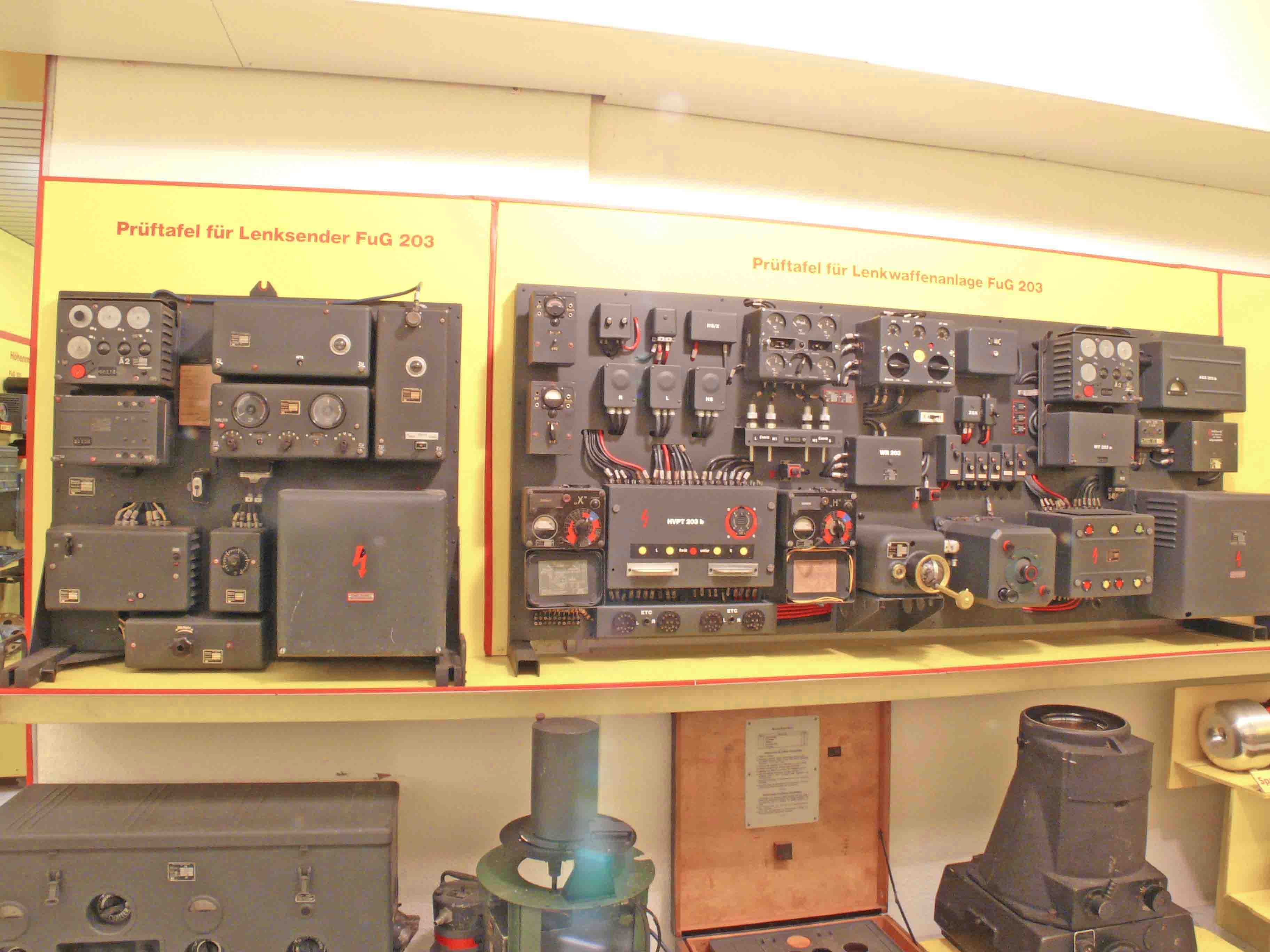
This wall shows from left to right: Prüftafel 203, used for testing transmitter S203 and its modulator; Prüftafel und Übungstafel, for testing and educational purposes, of FuG203 (TX) and FuG 230 (RX). To get an idea of its size, this test-table is about 2 meter wide! Marked with a 'yellow ring' is the 'joystick' of this system. Beck showed me, however, three different types (one or two being employed for wire-controlled guidance). It also had test facilities for checking the so-called Abreißstecker, called 'Jatow Stecker'. A special connector designed as to facilitate tight plug-connections, though, when force under an angle is brought on it, it very easily disconnects itself (Brechkopplung)

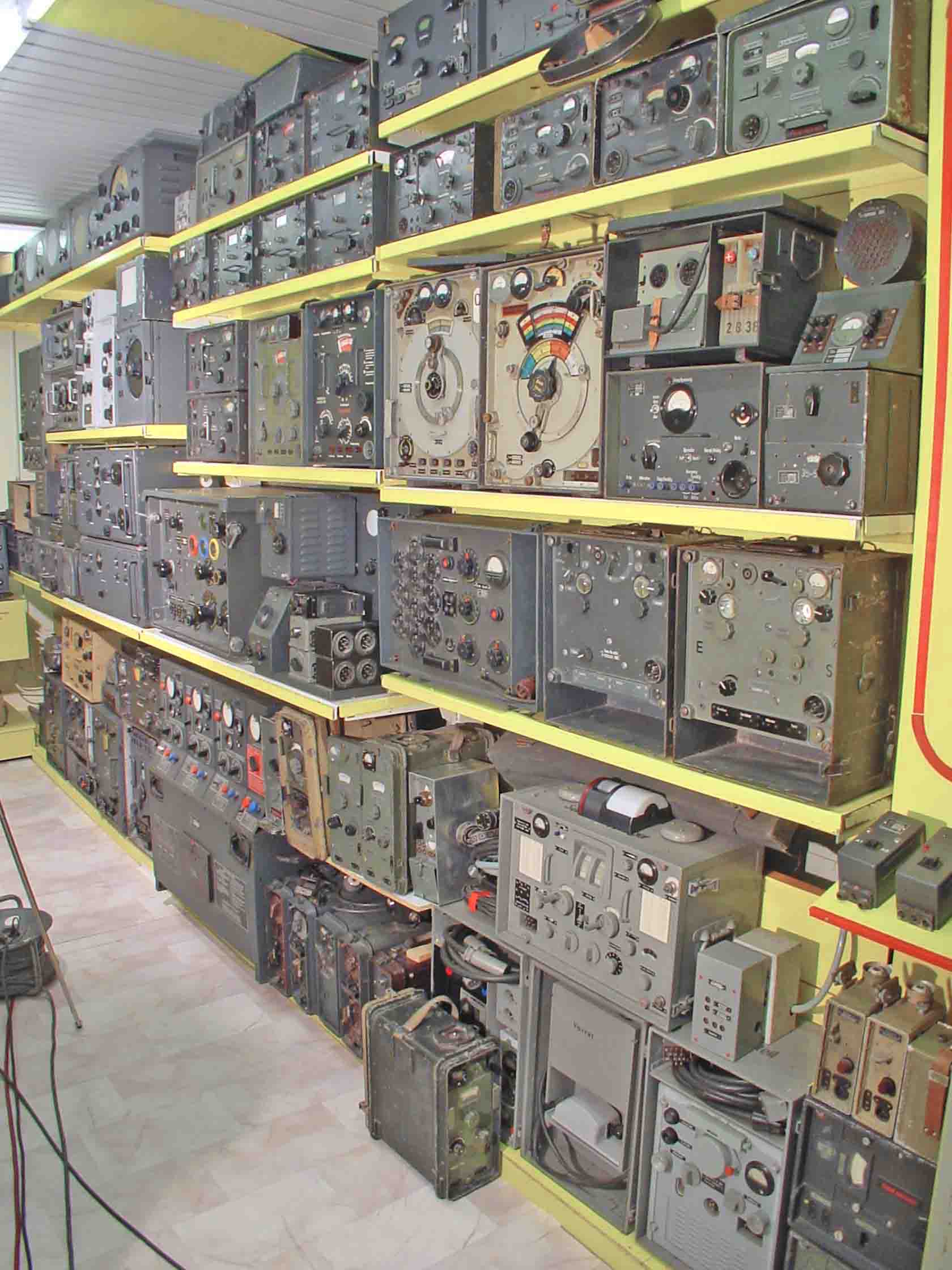
The upper two rows show a wide range of 'Funkhorchempfänger' (interception receivers), the third shelf from left to right, Main receiver T9K39 with attached naval DF unit, Lorenz type V3 receiver, ?, FuPeil a/b and/or c, Hüttenpeiler with attached DF-goniometer, Torn Fu. H(a?), Ton Fu. b or f (Photo Beck)
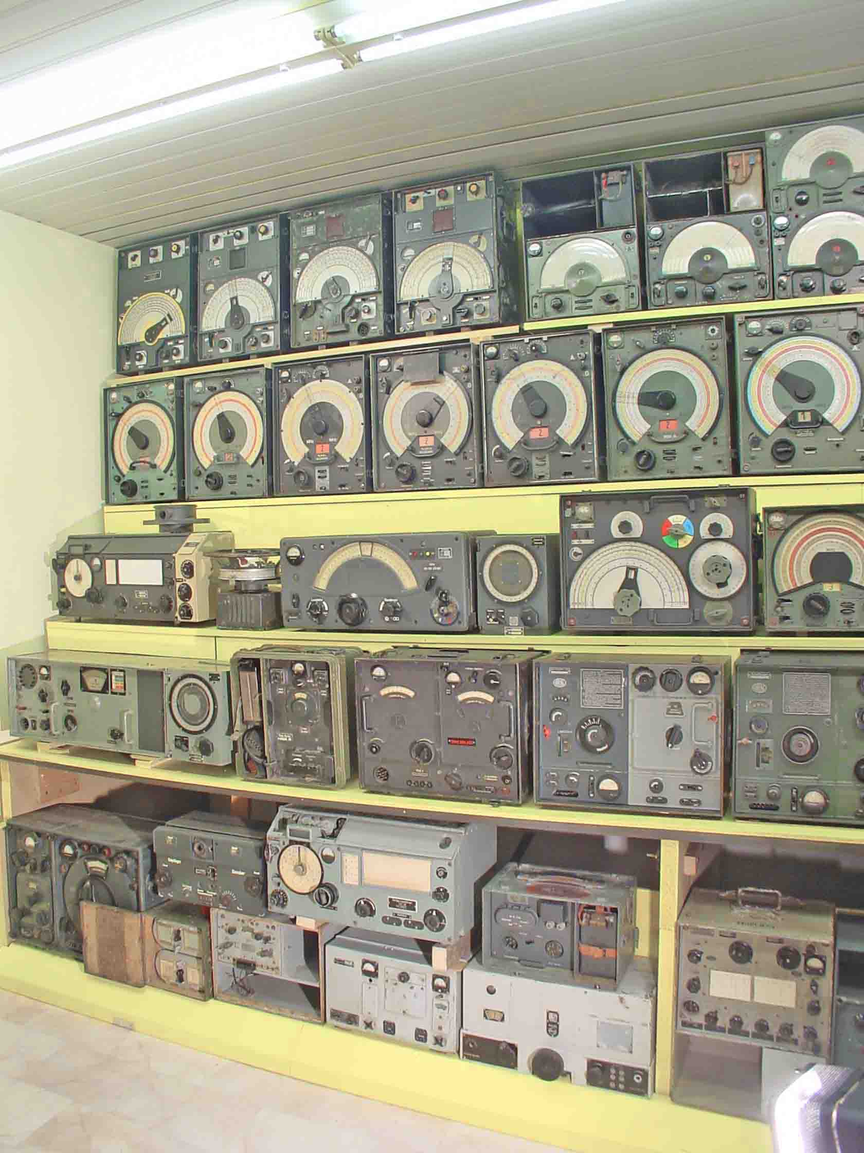
Vey low, pre-war set, FuG 16 or 17, Philips/NSF Ph1uk41/DR25a, Philips/NSF DR38, on top Wupper T8L39, Philips/NSF H2L7, on top power supply to 15 WSb, Ha15K42 (Photo Beck)
Beck's so-called Heeres (= Army) display section. We should not take this too literally, as he also shows some Navy sets. In the middle with the three coloured meter-rings transmitter AS59, right of it the 'Greatz version to the Y-distance-measuring system'. (Photo Beck)

Horst Beck's display of V2 related gyros (= Kreisel) and auxiliarly devices. Seen from left to right first - second and third gyro generation. The upper shelves show on the left axis gyros on the right Kommando-Empfänger Victoria, which was the radio controlled command receiver of the V2 rocket. Which wasn't fit when this weapon was aimed at enemy targets (Photo Beck)
*To get entire displays at one picture, I have often used an extreme wide-angle lens-adapter, which gives some barrel distortion. Though, there is no way, regarding the limited space, to overcome this with my Leica equipment
![]()